Your project is on hold because two flanges just won't line up. This common problem costs time and money. Here are the professional solutions you need for every situation.
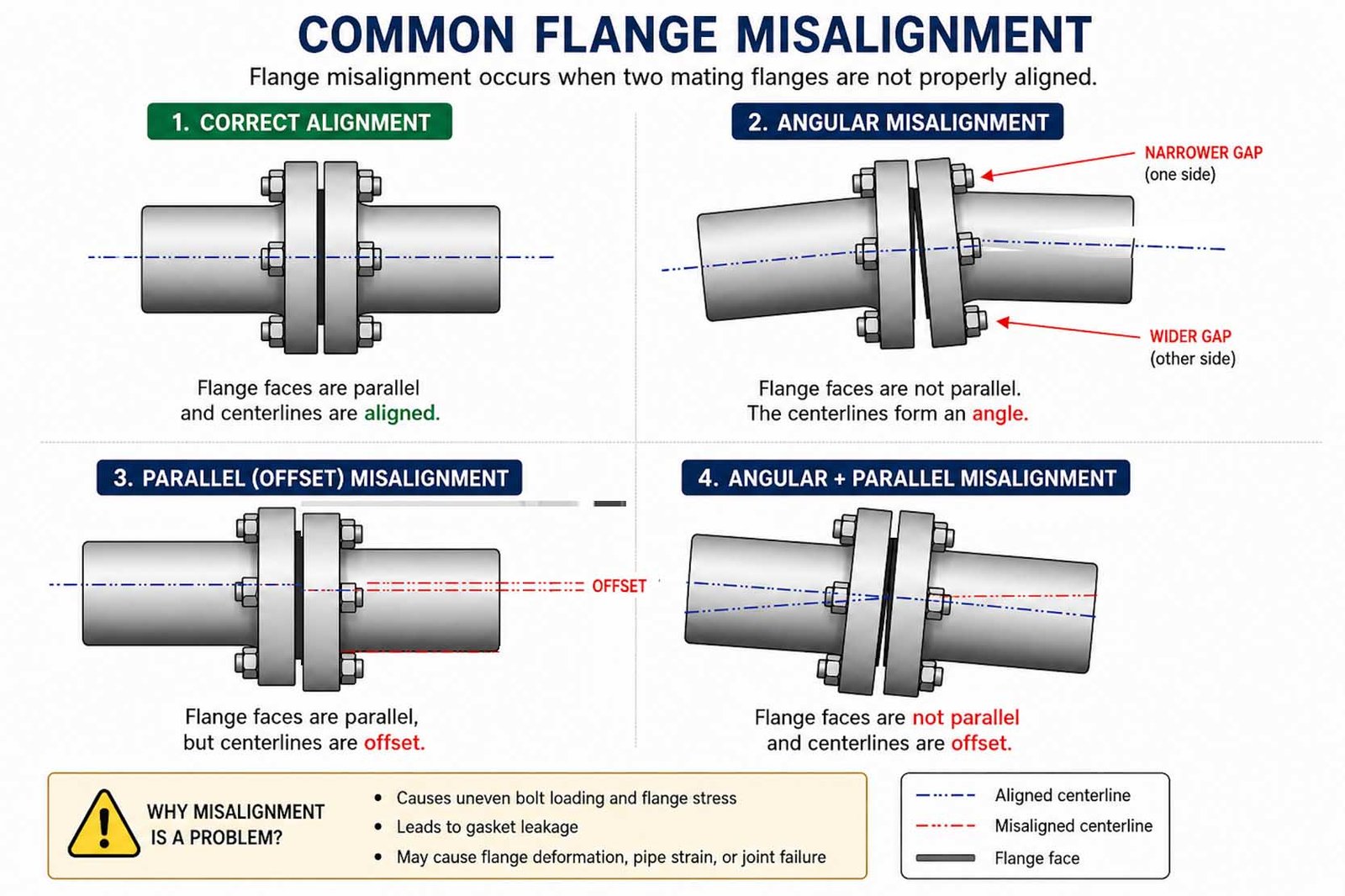
Flange misalignment occurs when flange faces are not parallel or the bolt holes are not aligned. To fix this, you must identify the cause and use the correct fitting, such as a reducer flange for size differences or a spacer for gaps, without forcing the connection.
We've been manufacturing pipe fittings for 30 years, and I've seen every possible alignment issue on job sites. These problems can seem complex, but they all have a correct engineering solution. Forcing a connection is never the answer; it only leads to leaks, stress, and failure down the line. Let's break down each problem one by one so you can get your project back on track safely and efficiently.
What Should You Do When There's a Gap Between Flanges?
You have a gap between two flanges that should meet. You know pulling the pipes together will create dangerous stress. The right component is needed to solve this properly.
To fix a gap between flanges, you must use a custom-made filler flange or a flange spacer. This component is designed to fit the exact gap distance, allowing the flanges to be bolted securely without adding any stress to the pipeline.
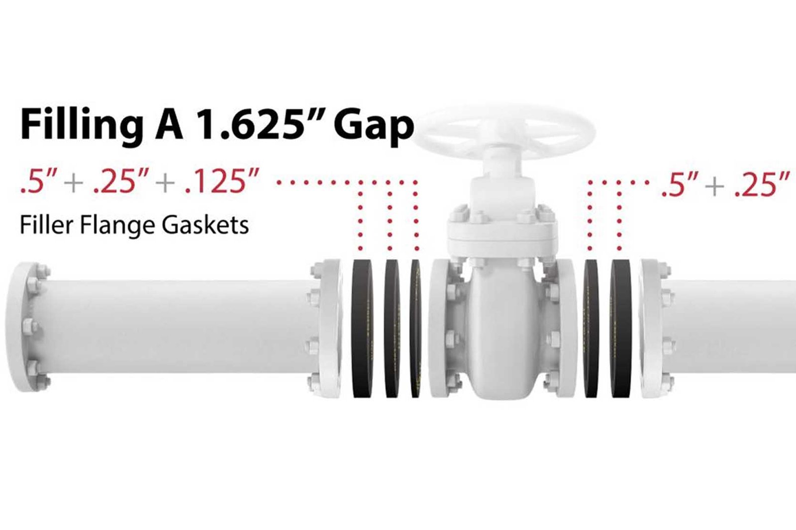
When faced with a parallel gap, the worst thing you can do is use longer bolts to pull the pipes together. This introduces enormous stress on the flanges, the pipe welds, and any connected equipment like pumps or valves. I once saw a pump casing crack just weeks after installation because the contractor forced a 10mm gap to close. The stress was too much. The correct solution is to precisely measure the gap and order a spacer.
Spacer vs. Filler Flange
While the terms are often used together, they can mean slightly different things.
- Flange Spacer: A simple ring, often called a paddle spacer, with the same inner and outer diameter as the flange. It fits between the raised faces.
- Filler Flange: A more robust piece, essentially a very short piece of pipe with two flanges welded on it. This is used for larger gaps.
The choice depends on the size of the gap and the pressure in the system. For any solution, material compatibility is key. The spacer must be made from a material that is compatible with the flanges and the fluid inside the pipe to prevent corrosion.
| Feature | Flange Spacer | Filler Flange |
|---|---|---|
| Best For | Small gaps (e.g., < 50mm) | Large gaps |
| Construction | Solid metal ring | Fabricated spool piece |
| Pressure | Good for most pressures | Excellent for high pressure |
| Cost | Lower | Higher |
Always measure the gap at multiple points to ensure it's parallel before ordering your spacer.
How Can You Connect Flanges with Different Sizes?
You need to connect a DN100 pipe to a DN150 line. The flanges obviously don't match. This is a common requirement in plant modifications, but it needs a specific solution.
To connect flanges of different nominal sizes, you must use a reducer flange. This is a single, specialized flange with the outer diameter and bolt pattern of the larger flange but a bore matching the smaller pipe, ensuring a smooth transition.
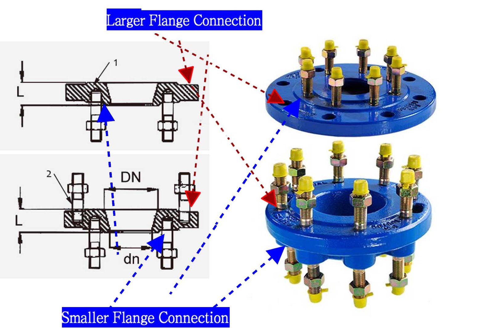
A reducer flange, sometimes called a reducing flange, is the cleanest and most professional way to solve this problem. It's a one-piece solution that eliminates the need for extra components. The alternative would be to use a standard flange, a pipe reducer (concentric or eccentric), and then another standard flange. This old method adds two extra welds and two more potential leak points to the system. In our factory, we can manufacture reducer flanges to any standard, ensuring the pressure rating and material match your project's specifications perfectly.
Key Considerations for Reducer Flanges
When you order or specify a reducer flange, you need to provide clear information.
- Larger Flange Size & Standard: For example, DN150 PN16 (EN 1092-1). This defines the outside diameter, thickness, and bolt pattern.
- Smaller Pipe Size: For example, to connect to a DN100 pipe. This defines the bore of the flange.
- Flange Face Type: Is it a Raised Face (RF) or Flat Face (FF)?
- Material: Ductile Iron, Carbon Steel, Stainless Steel, etc.
Using a reducer flange simplifies installation, reduces labor costs, and creates a stronger, more reliable connection. It's the modern engineering standard for connecting pipes of different sizes.
Can You Connect a Raised Face (RF) and a Flat Face (FF) Flange?
You have one flange with a raised face and another that is completely flat. Mating them seems risky. Will it seal, or will it break? This is a critical question, especially with brittle materials.
Yes, you can connect an RF and an FF flange, but it is highly discouraged for brittle materials like cast iron. The pressure from the RF can crack the FF flange. The best practice is to machine the raised face off to create a flat surface.
The problem here is concentrated stress. The small surface area of the raised face puts a huge amount of pressure on the flat face flange when you tighten the bolts. If the FF flange is made of a strong material like forged steel, it can usually handle this stress. However, if it's made of a brittle material like cast iron or ductile iron—which is common in waterworks—this concentrated force can easily crack the flange. I have seen this happen. A technician over-torqued the bolts, and the flat face flange snapped.
The Correct and Safe Procedure
If you absolutely must connect an RF flange to an FF flange made of a brittle material, you have one safe option:
- Machine the RF Flange: Take the raised face flange to a machine shop.
- Remove the Raised Face: The machinist will remove the raised portion, making it a flat face flange.
- Install as FF to FF: Now you have two flat faces. You can install them using a full-face gasket, which spreads the bolt load evenly and ensures a safe, reliable seal.
This small amount of extra work prevents a catastrophic failure. Never take the risk of mating an RF flange directly to a cast iron or ductile iron FF flange.
How Do You Connect Flanges Made of Different Materials?
Your design calls for a stainless steel pipe to connect to a ductile iron valve. You know that joining dissimilar metals can cause problems. How do you prevent corrosion and ensure a long service life?
To connect flanges of different materials (e.g., ductile iron to stainless steel), you must use a flange isolation kit. This prevents galvanic corrosion by electrically isolating the two metals from each other.
When two different metals are in contact in the presence of an electrolyte (like water), they form a small battery. One metal (the anode) corrodes much faster than it normally would, while the other (the cathode) is protected. This is called galvanic corrosion, and it can destroy a pipeline. I've seen carbon steel flanges connected to stainless steel turn to rust in a surprisingly short time. The solution is to break the electrical circuit.
Components of a Flange Isolation Kit
A standard flange isolation kit creates a barrier between all the metal components.
- Isolating Gasket: A gasket made from a non-conductive material. It has the same dimensions as a standard gasket but prevents metal-to-metal contact between the flange faces.
- Bolt Sleeves: Non-conductive sleeves that slide over the bolts. This prevents the bolts from touching the inside of the bolt holes on one of the flanges.
- Isolating Washers: Non-conductive washers that sit under the steel washers and nuts. This prevents the nuts and washers from touching the flange surface.
By using all three components, you create a fully isolated connection. The flanges, bolts, and nuts never make direct contact, stopping galvanic corrosion before it can start. This is essential for the long-term health of any mixed-material pipeline.
What Should You Do When Flange Bolt Holes Don't Align?
The pipe is in place, but the flange bolt holes are slightly off. It seems like you could just use a drift pin or a pry bar to force them into place. This is a tempting shortcut, but it's one of the most dangerous.
If flange bolt holes do not align, stop. Never force them. The root cause is pipe misalignment, which must be corrected first. Forcing the connection introduces extreme stress that will lead to leaks, damage, and potential failure.
Forcing misaligned flanges together is called residual loading. You are essentially pre-loading the system with a huge amount of stress before it even sees any operational pressure or temperature changes. This hidden stress is a ticking time bomb. It can lead to:
- Cracked welds near the flange.
- Damage to the bearings and seals of connected equipment, like pumps.
- Warped flanges that can never seal properly.
- Fatigue failure over time.
As a manufacturer, we guarantee the dimensions of our fittings. If the bolt holes don't align, the problem is almost always in the pipe installation.
How to Fix the Root Cause
Instead of forcing the bolts, you need to fix the pipe's position.
- Loosen Supports: Go back along the pipe run and loosen the pipe supports.
- Adjust the Pipe: Gently shift the pipe until the flange faces are parallel and the bolt holes align naturally. You should be able to slide the bolts through by hand.
- Use Proper Tools: Use tools like levels, squares, and laser alignment systems to ensure the pipe is correctly positioned.
- Re-tighten Supports: Once the alignment is perfect, re-tighten the supports to hold the pipe in its new, stress-free position.
This takes more time upfront, but it ensures the safety and reliability of the entire system.
Can Expansion Joints Be Used to Fix Flange Misalignment?
You have a significant misalignment, maybe both a gap and an angular error. An expansion joint looks like a flexible, easy solution to bridge that gap. But is this what they are designed for?
No, you must never use an expansion joint to correct static installation misalignment. Their purpose is to absorb dynamic operational movements like thermal expansion and vibration. Using one for misalignment will cause it to fail quickly.
This is one of the most critical and costly mistakes I see in piping installation. An expansion joint is a finely engineered component designed to flex and move hundreds or thousands of times during its service life. If you install it stretched, compressed, or twisted to make up for poor pipe fitting, you are using up all its movement capability before the system even starts. It's like pulling a rubber band as tight as it will go and then expecting it to stretch even more. It can't. The joint will be under constant stress, leading to premature failure of the rubber or metal bellows.
Static Misalignment vs. Dynamic Movement
It's crucial to understand the difference.
- Static Misalignment: This is an installation error. The pipes are in the wrong place. This must be fixed by correcting the pipework.
- Dynamic Movement: This is movement that occurs when the system is operating. It is caused by things like the pipe getting hotter or colder (thermal expansion/contraction) or vibrations from a pump.
Expansion joints are designed only for dynamic movement. The pipeline must be perfectly aligned before you install the expansion joint. The joint should be installed in a neutral, stress-free state so it is ready to absorb the movements it was designed for.
What Happens If Flange Standards Don't Match (EN vs. ANSI vs. JIS)?
You have two flanges. Both are the same size, let's say 4 inches or DN100. Both have the same pressure rating. But one is made to an ANSI standard and the other to an EN standard. They should connect, right?
Flanges made to different international standards (like EN, ANSI, JIS, AS/NZS) are generally not interchangeable, even if they have the same nominal size. Key dimensions like the bolt circle diameter (PCD), number of bolts, and bolt hole size will be different.
This is a very common source of frustration on international projects. A flange is not just defined by its pipe size. It is a complete system of dimensions. Even a small difference in the bolt circle diameter means you cannot connect the two flanges. As a manufacturer that ships globally, we have to be experts in these standards. We always ask our clients to specify the exact standard and pressure class they need.
Example: DN100 / 4" Flange Comparison
Let's look at a real-world example to see why they don't match.
| Dimension | ANSI B16.5 Class 150 | EN 1092-1 PN16 | JIS B2220 10K |
|---|---|---|---|
| Flange OD | 228.6 mm | 220 mm | 210 mm |
| PCD | 190.5 mm | 180 mm | 175 mm |
| No. of Bolts | 8 | 8 | 8 |
| Bolt Hole Dia. | 19.1 mm (for 5/8" bolt) | 18 mm (for M16 bolt) | 19 mm (for M16 bolt) |
As you can see, none of the critical dimensions match. The PCD is different in all three, making a connection impossible. The only solution is to use an adapter flange or replace one of the flanges with one that matches the correct standard for the rest of the pipeline. Always check the engineering drawings and specifications.
Can You Drill New Holes in a Flange to Make It Fit?
The flange almost fits, but the bolt holes are just a few millimeters off. It seems so easy to just put it on a drill press and drill new holes where you need them. Is this a safe or acceptable practice?
No, you should never drill new holes in a standard, certified flange. This action destroys its structural integrity, voids its pressure certification and warranty, and creates a serious safety hazard that could lead to catastrophic failure.
A flange is an engineered product. Its design, including the thickness and the spacing of the bolt holes, has been calculated and tested to withstand specific pressures. The material between the bolt holes is critical for containing the pressure and maintaining a seal. When you drill a new hole, you are removing material from this critical area. This creates what are called "stress concentrations." The metal around the new, non-standard hole is now a weak point. Under pressure, this is where a crack will start.
Why It's a Terrible Idea
- Structural Weakening: You are fundamentally weakening the flange. It can no longer be trusted to hold its rated pressure.
- Voided Certification: The flange is no longer compliant with the standard it was manufactured to (e.g., EN, ANSI). In case of an accident, your company would be fully liable.
- Gasket Sealing Issues: Drilling can damage the raised face or create an uneven surface, making it impossible for the gasket to create a proper seal.
- No Traceability: No reputable manufacturer would ever approve of this. The part is now a custom, uncertified component.
The only professional solution is to get the correct flange for the job. The small cost of a new flange is nothing compared to the cost of an accident, downtime, and potential injury caused by a modified, weakened part.
Can a Bad Torque Sequence Cause “Fake Misalignment”?
The flanges were perfectly aligned before you started bolting. As you tightened them, a gap opened up on one side. It looks like the flanges are now misaligned, but what really happened?
Yes, an incorrect bolt tightening procedure will cause the flanges to pull together unevenly, creating angular misalignment or a "fake misalignment." Always use a star or crisscross pattern and multiple stages to ensure even pressure on the gasket.
This is an incredibly common installation error. Many technicians will simply tighten the bolts in a circle, one after another. This puts all the pressure on one side of the gasket first, crushing it while the other side is still loose. As they continue, the flange pivots on this crushed section, creating a gap on the opposite side. The installer might then try to close this new gap by over-torquing the bolts, which can damage the gasket, the bolts, or even the flange itself. I've seen gaskets pushed out from between flanges because of this.
The Correct Bolting Procedure
To prevent this and ensure a perfect seal, you must apply pressure evenly.
- Hand-Tighten: Install all bolts and hand-tighten the nuts.
- Use a Star Pattern: Number the bolts like a clock face. For an 8-bolt flange, tighten in the order: 1, 5, 3, 7, 2, 6, 4, 8. This crisscross pattern distributes the load evenly.
- Tighten in Stages: Don't go to full torque in one pass.
- Pass 1: Tighten each bolt in the star pattern to about 30% of the final torque value.
- Pass 2: Repeat the pattern to 60% of the final torque.
- Pass 3: Repeat the pattern to 100% of the final torque.
- Final Pass: Do one final circular pass to ensure all bolts are at a uniform torque.
This methodical approach ensures the flange faces come together perfectly parallel, compressing the gasket evenly for a leak-free, long-lasting seal.
Conclusion
Proper flange alignment is about safety and long-term reliability. Always identify the specific problem and use the correct engineering solution and technique, never force a connection.
