
Ultragrip Heavy Duty Restrained Wide Range Flange Adaptor Installation Guide
Installation Guide
Select the appropriate product according to the range marking on the end ring of the Judberd ULTRAGRIP Heavy-Duty Restrained Wide-Range Flange Adaptor. Ensure that the outside diameter of the pipe falls within the range specified by Judberd, as indicated below. Before installation, carefully read these installation instructions and check that no components are missing or damaged.
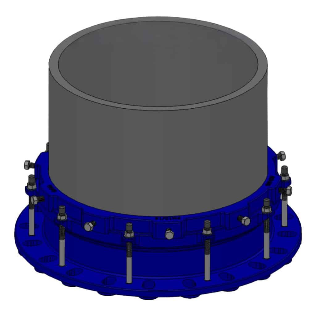
Note: An internal stiffener shall be installed in all HDPE pipes used with Judberd ULTRAGRIP Heavy-Duty Restrained Wide-Range Flange Adaptors. This is mandatory for SDR17 and thinner wall pipes (SDR21, SDR26, SDR33, SDR41), and strongly recommended for all HDPE pipe installations.
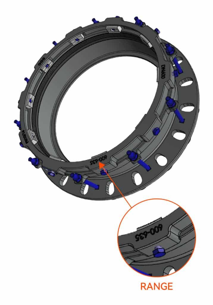
STEP 1
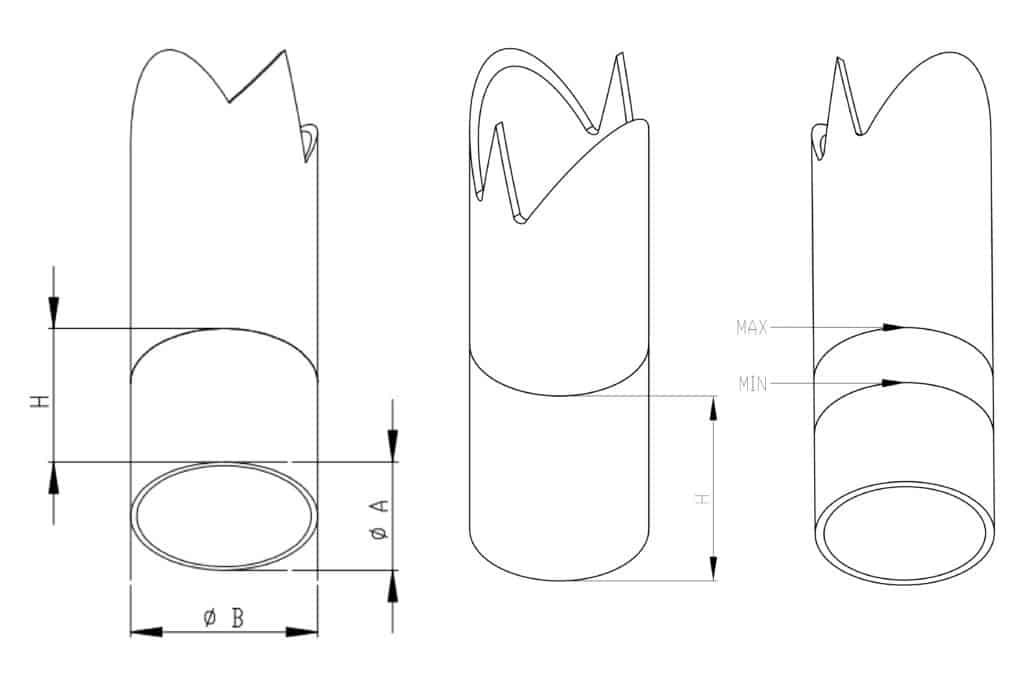
First, measure the outside diameter of the pipe to be connected. Measure the pipe in two perpendicular directions to obtain ØA and ØB, as shown in the figure below. Calculate the average value using (ØA + ØB) / 2 to determine the pipe diameter.
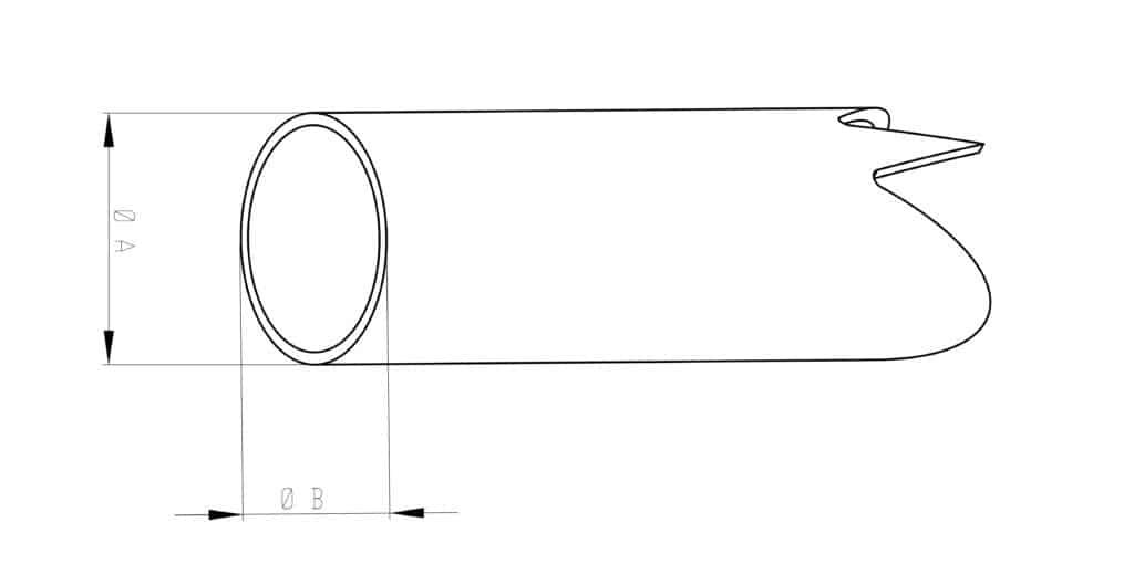
STEP 2
Measure the flange adaptor height (H) as shown in the figure below for later use.
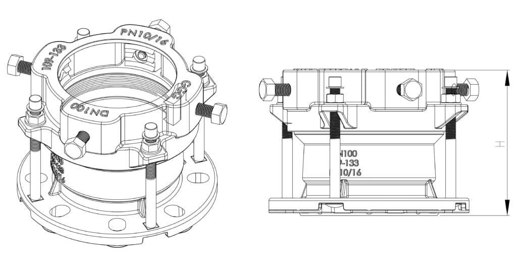
STEP 3
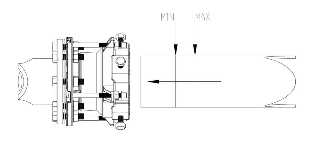
Clean the pipe end to be connected. The cleaned length shall be slightly longer than H. After cleaning, mark a MIN line (as shown in the figure below and in the parameter table for the minimum pipe insertion depth) and a MAX line (as shown in the figure below and in the parameter table for the maximum pipe insertion depth).
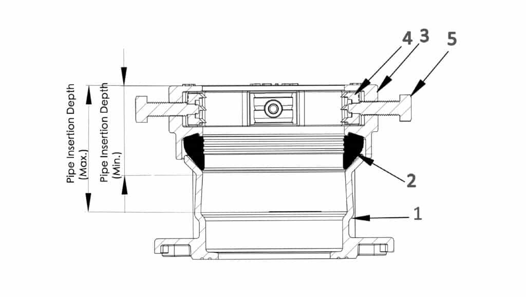
| DN | OD | PN | Pipe Insertion Depth (Min.) | Pipe Insertion Depth (Max.) |
|---|---|---|---|---|
| DN50 | 58-74 | PN10/16 | 85 | 115 |
| DN65 | 68-85 | PN10/16 | 85 | 115 |
| DN80 | 84-106 | PN10/16 | 85 | 115 |
| DN100 | 99-118 | PN10/16 | 85 | 140 |
| DN100 | 109-133 | PN10/16 | 85 | 115 |
| DN125 | 129-159 | PN10/16 | 90 | 140 |
| DN150 | 157-182 | PN10/16 | 85 | 125 |
| DN200 | 177-207 | PN10/16 | 90 | 160 |
| DN200 | 194-225 | PN10/16 | 90 | 160 |
| DN200 | 218-242 | PN10/16 | 85 | 130 |
| DN250 | 244-276 | PN10/16 | 90 | 140 |
| DN250 | 266-291 | PN10/16 | 90 | 130 |
| DN250 | 280-305 | PN10/16 | 90 | 120 |
| DN300 | 302-327 | PN10/16 | 90 | 130 |
| DN300 | 314-356 | PN10/16 | 105 | 160 |
| DN350 | 342-372 | PN10/16 | 105 | 180 |
| DN350 | 362-392 | PN10/16 | 105 | 180 |
| DN350 | 370-400 | PN10/16 | 105 | 160 |
| DN350 | 386-410 | PN10/16 | 105 | 160 |
| DN400 | 380-415 | PN10/16 | 105 | 190 |
| DN400 | 390-425 | PN10/16 | 105 | 190 |
| DN400 | 398-433 | PN10/16 | 105 | 190 |
| DN400 | 420-455 | PN10/16 | 105 | 160 |
| DN450 | 440-475 | PN10/16 | 105 | 190 |
| DN450 | 470-505 | PN10/16 | 105 | 160 |
| DN500 | 485-520 | PN10/16 | 105 | 200 |
| DN500 | 499-534 | PN10/16 | 105 | 200 |
| DN500 | 520-555 | PN10/16 | 105 | 160 |
| DN600 | 600-635 | PN10/16 | 105 | 200 |
| DN600 | 615-650 | PN10/16 | 105 | 200 |
Inspect the pipe surface from the pipe end to the MAX line and ensure that there are no obvious dents, protrusions, scratches, or other defects that may affect the sealing performance. All weld seams shall be ground smooth.
Please note that the pipe ovality (ØA − ØB) shall be less than 1.5 mm for pipes with an outside diameter up to OD400, less than 2.0 mm for pipes with an outside diameter from OD400 to OD600, and less than 2.5 mm for pipes with an outside diameter from OD600 to OD1000. If the measured ovality exceeds these limits, the pipe shall be re-rounded or reshaped to reduce the ovality to within the specified tolerances.
STEP 4
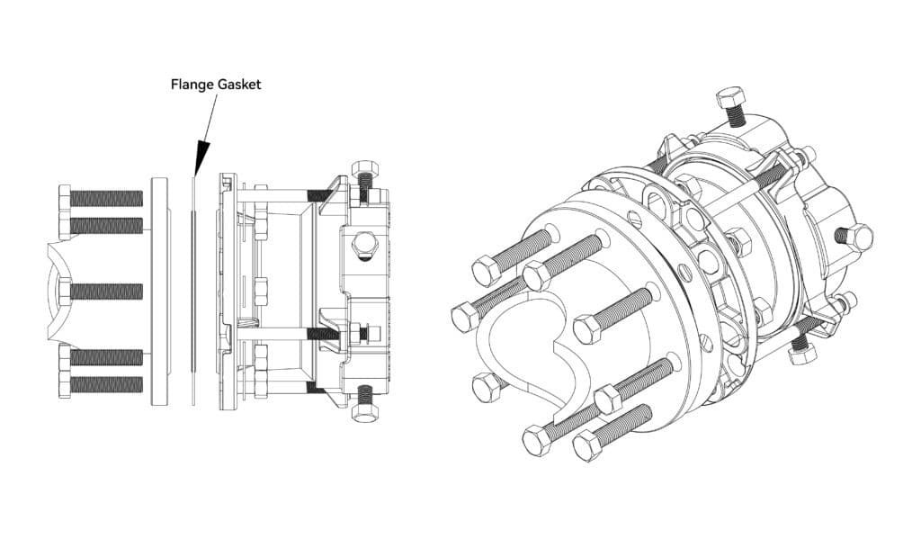
Select the appropriate flange gasket of the same size and place it between the flange of this adaptor and the mating flange, as shown in the figure below. Select bolts of the correct size and length (refer to the relevant flange standard for the required bolt dimensions) and align the flange bolt holes of the adaptor with those of the mating flange.
STEP 5
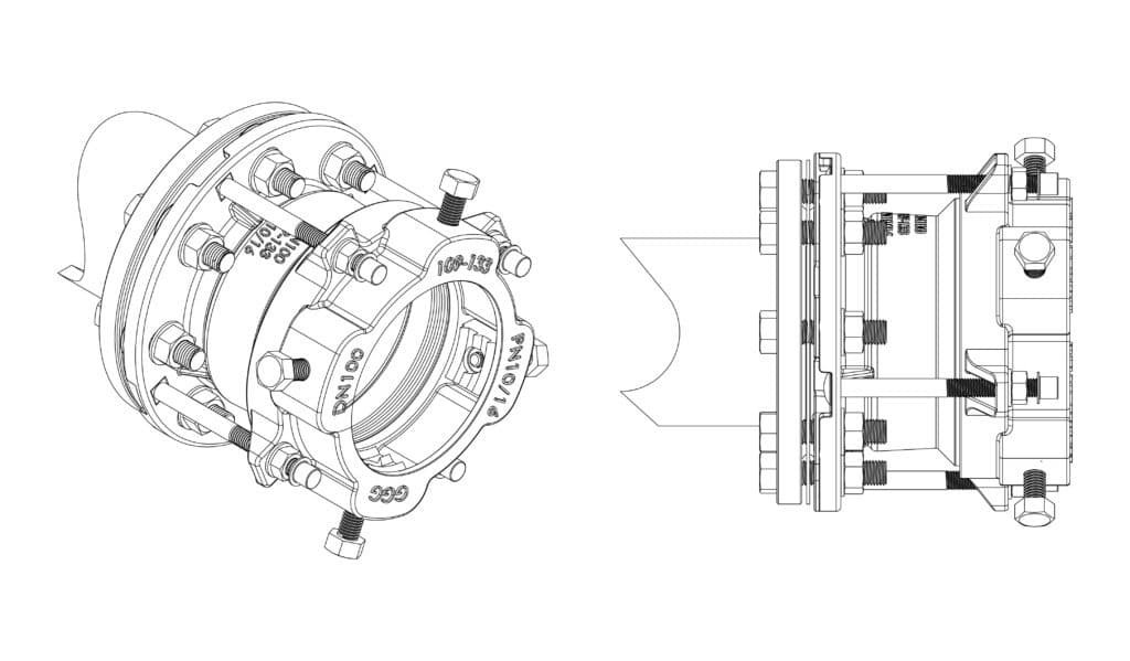
Insert the flange bolts and hand-tighten the nuts. Align the flange of this adaptor with the mating flange, then tighten all bolts gradually in several passes using a diagonal (cross-tightening) sequence.
STEP 6
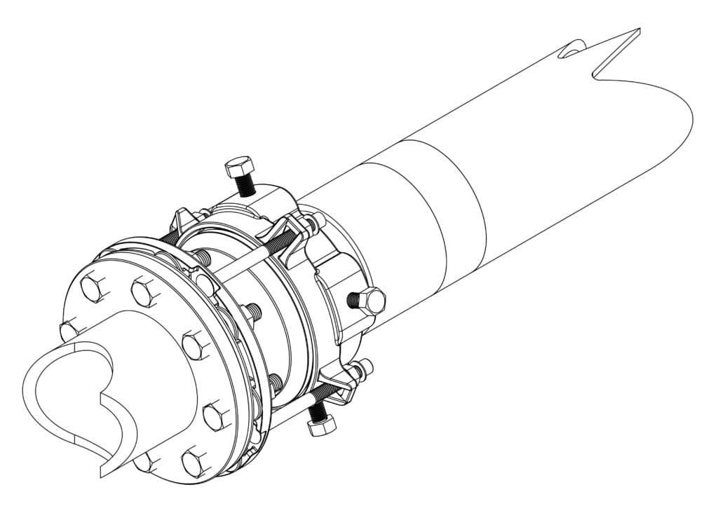
Our flange adaptor has been pre-assembled and lubricated. First, loosen and retract the side locking block bolts to prevent the locking blocks from obstructing pipe insertion. Loosen all gland nuts to facilitate the insertion of the pipe marked with the MIN and MAX insertion depth lines.
STEP 7
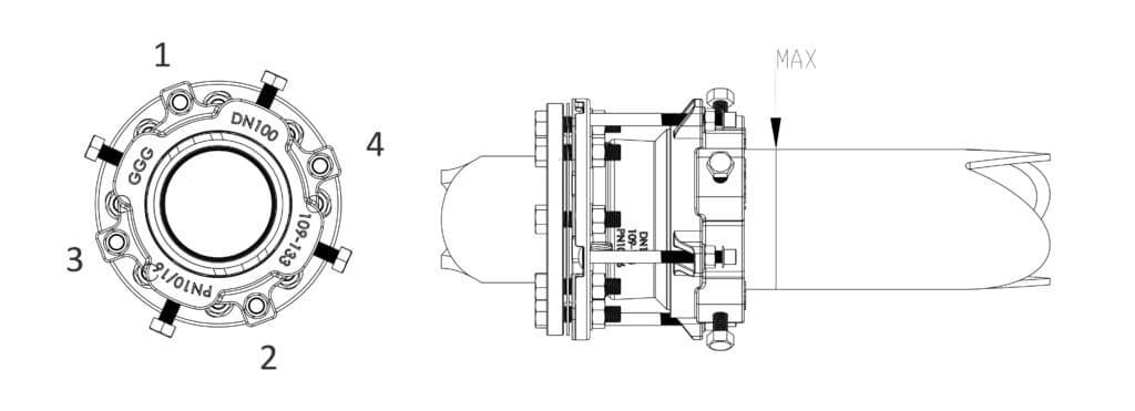
Insert the pipe until the MIN mark passes beyond the gland face, while ensuring that the MAX mark does not pass beyond the gland face.
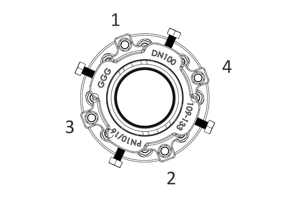
Tighten nuts 1, 2, 3, and 4 in several rounds using progressively increasing torque. The recommended tightening torques are as follows:
● M12: 40–50 N·m
● M14: 50–60 N·m
● M16: 60–70 N·m
STEP 8
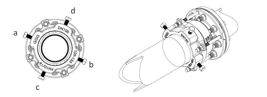
Tighten the side locking block bolts (a, b, c, and d) until each locking block makes light contact with the outside diameter of the inserted pipe.
After confirming that all locking blocks are in contact with the pipe OD, tighten the locking block bolts in multiple passes along the diagonal sequence of a-b-c-d, applying progressively increasing torque during each round.
STEP 9
To compensate for gasket settlement, retighten the gland nuts once more in the diagonal sequence of 1-2-3-4, using the same torque values specified below.
● M12: 40–50 N·m
● M14: 50–60 N·m
● M16: 60–70 N·m
STEP 10
To confirm that the installation has been completed correctly, perform a hydrostatic pressure test at 1.5 times the pipeline working pressure and inspect the joint for any signs of leakage.
