“Bell” refers to a bell-shaped (socket or coupling) connection, and “clamp” refers to a repair clamp . Therefore, a bell clamp is a repair clamp specifically designed for leaks at bell-shaped connections.In contrast, a standard repair clamp is designed to repair leaks on straight pipe sections.These two types of clamps are used for different repair locations.
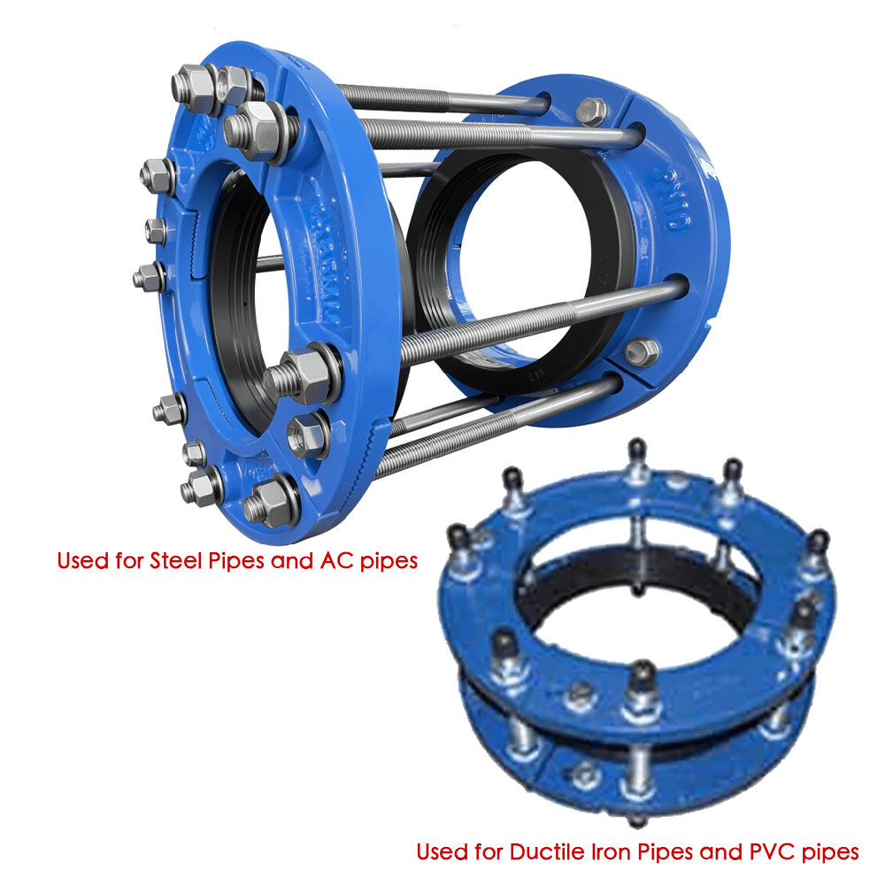
For pipes that use socket-and-spigot connections, such as ductile iron pipes and PVC pipes, leakage at the socket joint cannot be repaired with a standard repair clamp. For this reason, we have designed bell clamp specifically for leaks at socket-and-spigot joints, as shown in the picture below.
Specification
Wide range, can be used to repair socket-and-spigot joints leaking of many different pipes
For pipes that cannot be directly connected by socket-and-spigot joints, such as steel pipes and AC (asbestos cement) pipes, a coupling is usually required to connect the spigot ends of two pipes. However, leakage at both ends of the coupling also cannot be repaired with a standard repair clamp. Therefore, we have designed a bell clamp that can repair leaks at both ends at the same time, as shown in the picture below.
Specification
Wide range, can be used to repair coupling –spigot joints leaking of many different pipes
When using a bell clamp for pipeline repair, the repair can be carried out while the pipeline is working, avoiding pipeline shutdown.
Working priciple
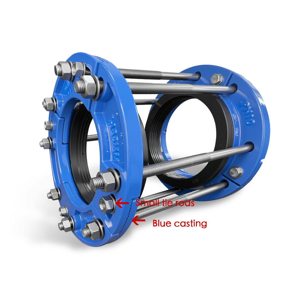
1. Use small bolts (as shown in the picture, small tie rods) to connect the castings (as shown in the picture, blue castings) together, forming a circular ring. This ring needs to have slight expandability, but the expansion range should be very limited.
2. Tighten the long bolts to clamp the castings together, as shown in the picture.
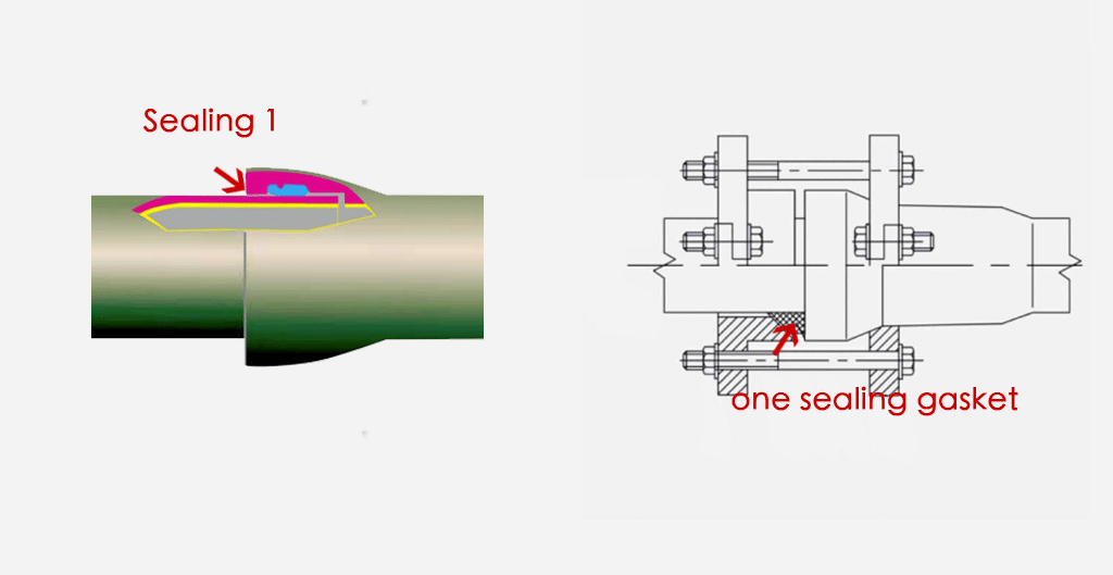
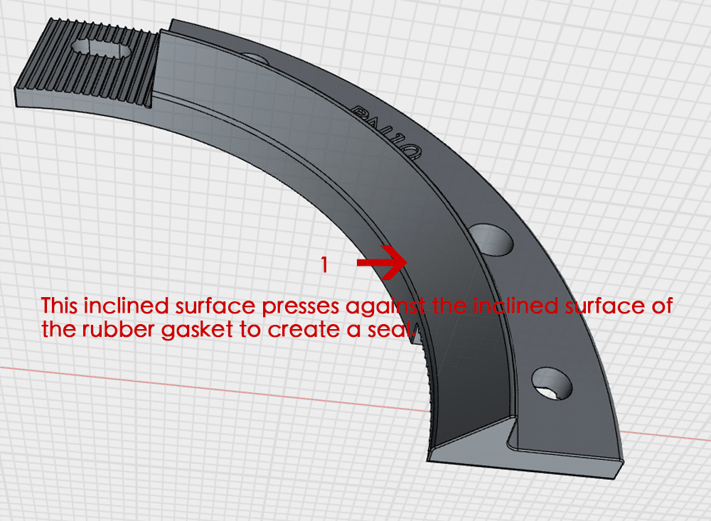
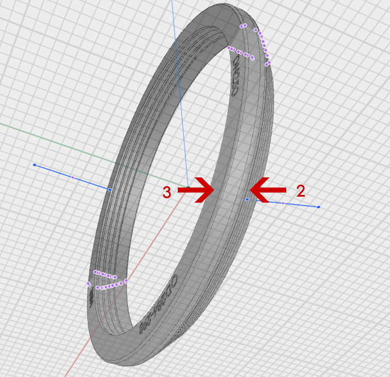
The inclined surface of the casting (see Figure 1) presses against the inclined surface of the rubber gasket (see Figure 2). This action forces the flat surface of the gasket (see Figure 3) to firmly press against the flat surface of the bell joint leakage area, creating a reliable seal.
Instruction video
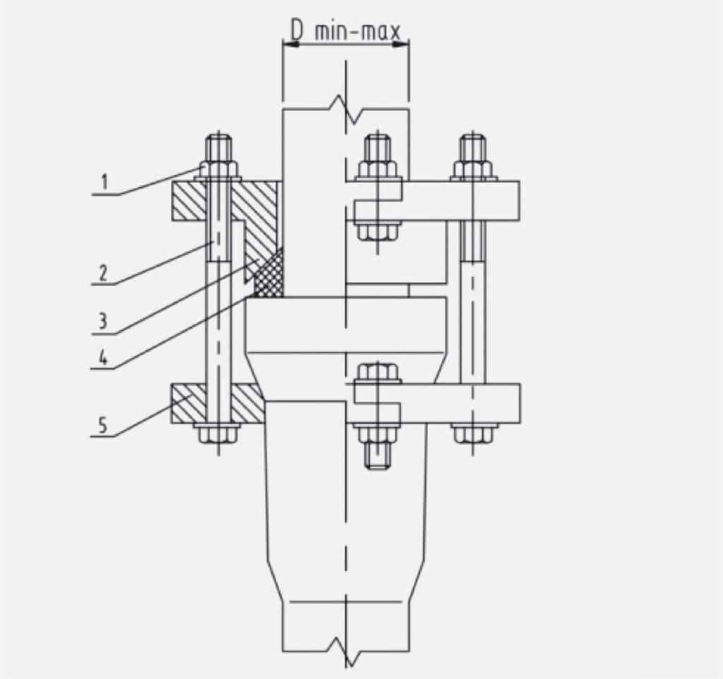
Drawing
Take 1st type as example, if you need drawing for 2nd type, please contact us.
Material
No.
Parts Name
Material
1
Nut
Gal.carbon steel
2
Bolts
Gal.carbon steel
3
Spigot ring
Ductile iron
4
Gasket
EPDM
5
Bell ring
Ductile iron
Dimension
DN
Range Dmin-max(mm)
50
62-68
65
75-84
80
94-100
100
114-120
150
166-173
200
217-224
250
270-276
300
321-328
350
373-380
400
424-431
500
527-534
600
630-638
Installation
Take 1st type as example, if you need installation guide for 2nd type, please contact us.
Step 1
Check the pipe’s outer diameter against the range marked on the Judberd bell clamp (the range is clearly marked on the casting). Make sure the bell clamp you select can accommodate the pipe’s outer diameter. Refer to Judberd’s bell clamp drawing to make sure all the components are there and in good condition.
Pay special attention to the rubber gasket—it must be brand new and in perfect condition. The quality of the gasket directly affects the performance of the entire product.
Step 2
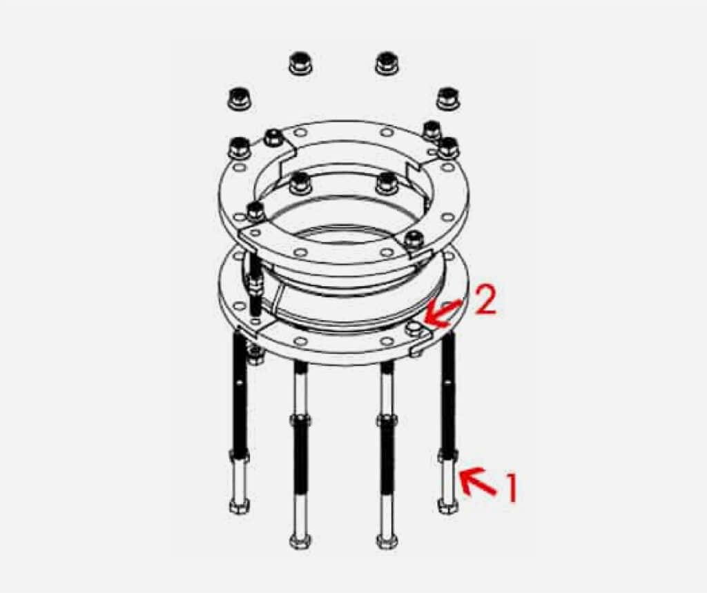
Take all the long bolts apart (as shown in Image 1).
For the short bolts (as shown in Image 2), take them apart based on the situation.
If a short bolt does not get in the way of putting the bell clamp on the pipeline, you can leave it in place.
Step 3
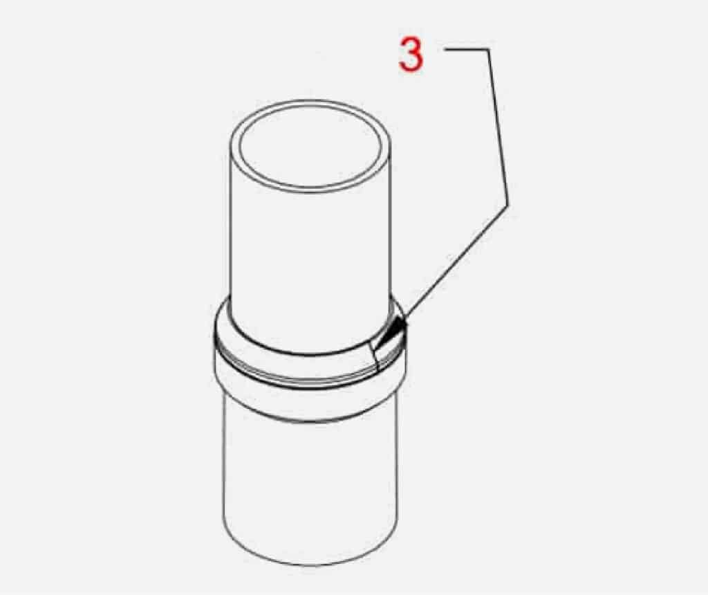
Wrap the rubber strip (as shown in Image 3) around the outer diameter of the spigot pipe (note: it must be the spigot pipe, not the socket pipe).
Check the length. If it’s too long, cut off the extra. Then use adhesive to connect the ends of the rubber strip together.
Step 4
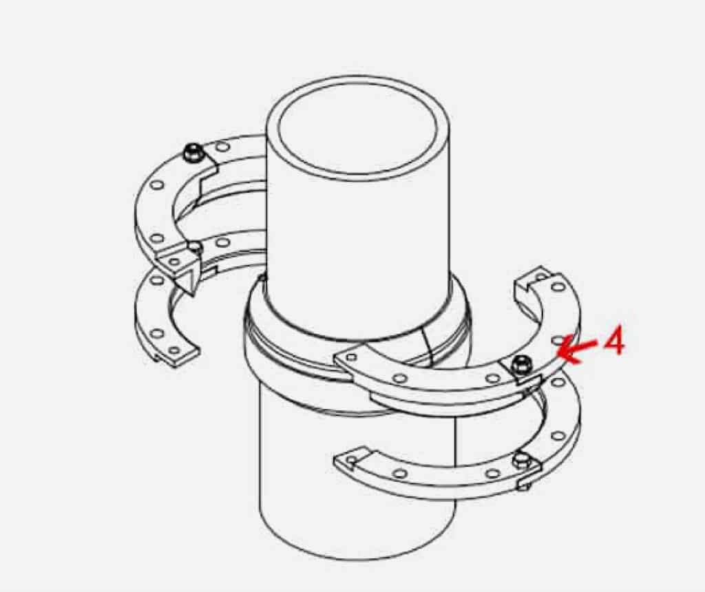
Snap the bell ring (shown in Figure 4) onto the outside of the pipe.
Step 5
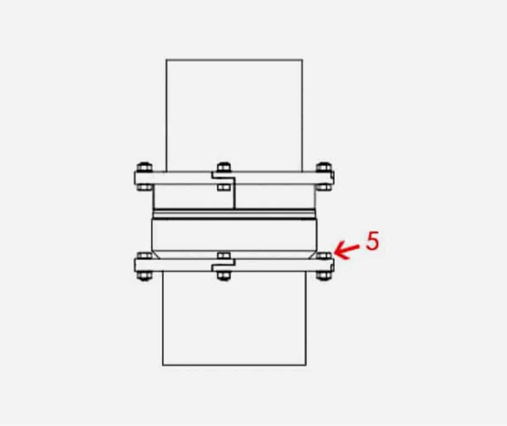
After you snap the bell rings onto the outside of the pipe, put the short bolts (shown in Figure 5) through the bolt holes and tighten them one by one at a time.
Please refer to the Judberd installation manual for the recommended torque.
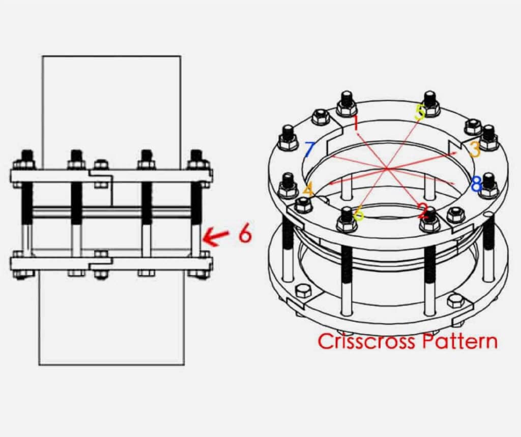
Step 6
Put the long bolts (shown in Figure 6) through the bolt holes one by one and tighten them to the required torque in multiple rounds using a crisscross pattern with even force.
Please refer to the Judberd installation manual for the recommended torque.
Step 7
Pressure test the system at 1.5 times the required working pressure.
If you have any leaks, go back to Steps 5 and 6 to make sure all the bolts are tight, then pressure test it again.
Keep doing this until you can pressure test the system at 1.5 times the required working pressure with no leaks.
Do You Need Our Catalogue to Check More?
Please Leave Us Your Information as Below,We will send you our Professional Catalogue As Soon As We Can
Need a quotation?
I’m Here
To Assist You
Please leave your enquiry,We will reply you in 24 hours.