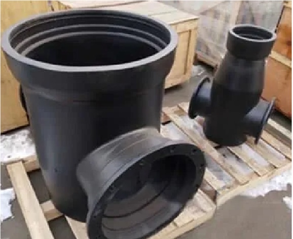
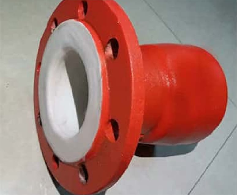
Ductile pipe fittings is the abbreviation of ductile iron pipe fittings , they are components used in piping systems to connect, divert, or otherwise manage the flow of fluids (usually water or sewage) through ductile iron pipes. These fittings are made from ductile iron, a type of cast iron known for its improved strength, flexibility, and impact resistance compared to traditional cast iron.
Judberd is a chinesemanufacturer for ductile pipe fittings, our ductile iron fittings are classified as EN545/ISO2531 ductile iron fittings for water supply and irrigation, AWWA C110 and AWWA C153 ductile iron fittings for water supply and irrigation, EN598 ductile iron fittings for sewage and AS/NZS 2280 ductile iron fittings for water supply and irrigation in Australia, new Zealand and Fiji , EN12842 ductile iron fittings for PVC pipe and EN545/ISO2531 loose flange ductile iron fittings. Judberd is specially competitive for MJ fittings, also called mechanical joint fittings. Details as below
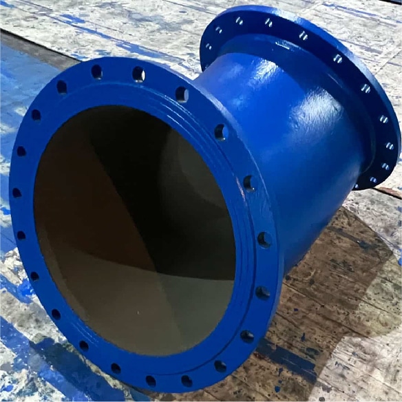
EN545/ ISO2531 DUCTILE IRON PIPE FITTING
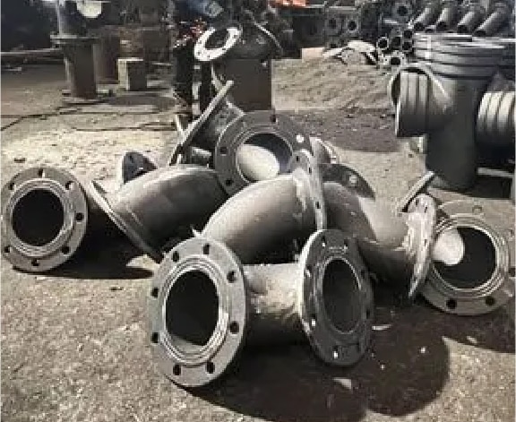
Judberd can produce ductile iron pipe fittings include but not limit to below type, if you have enquiry sheet, welcome you contact judberd.
Judberd can produce all ductile iron pipe fittings according to AWWA C110, include but not limit to below type, if you have enquiry sheet, welcome you contact judberd.
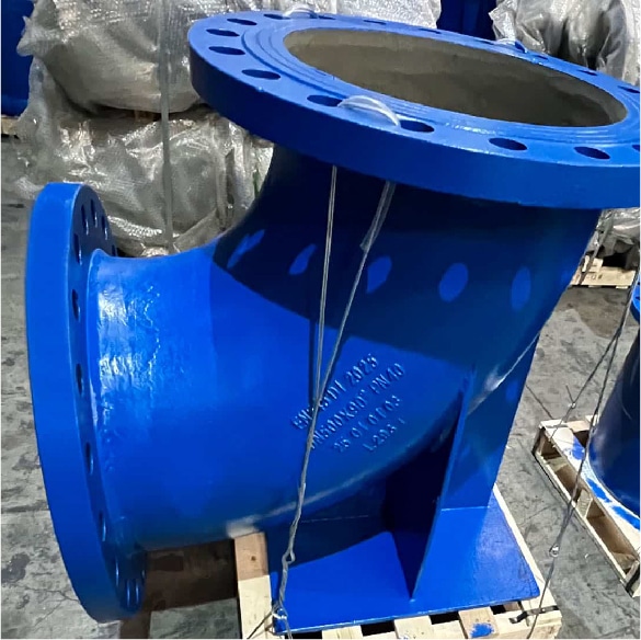
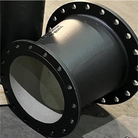
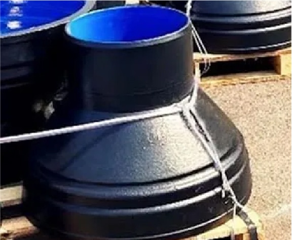
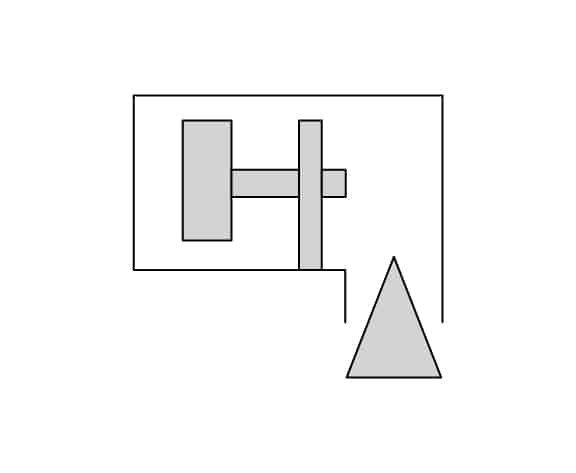
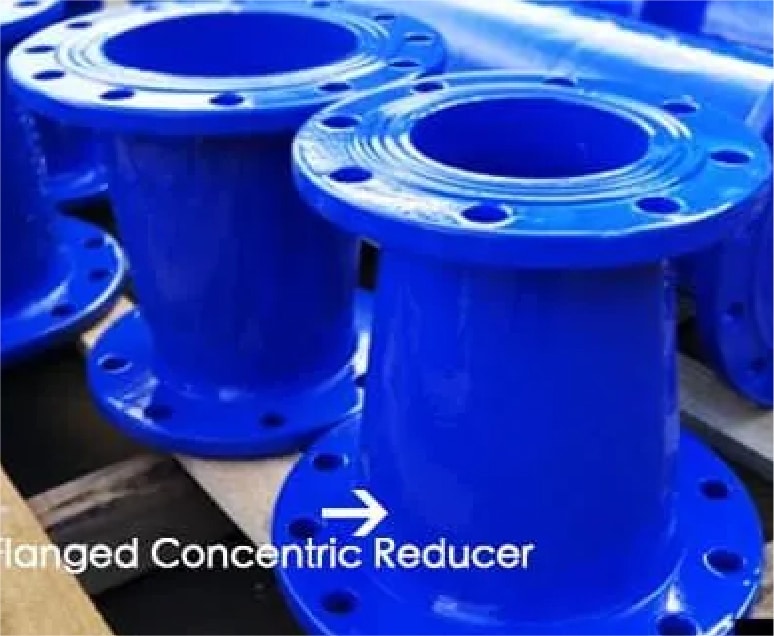
CONCENTRIC AND ECCENTRIC REDUCERS
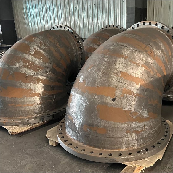
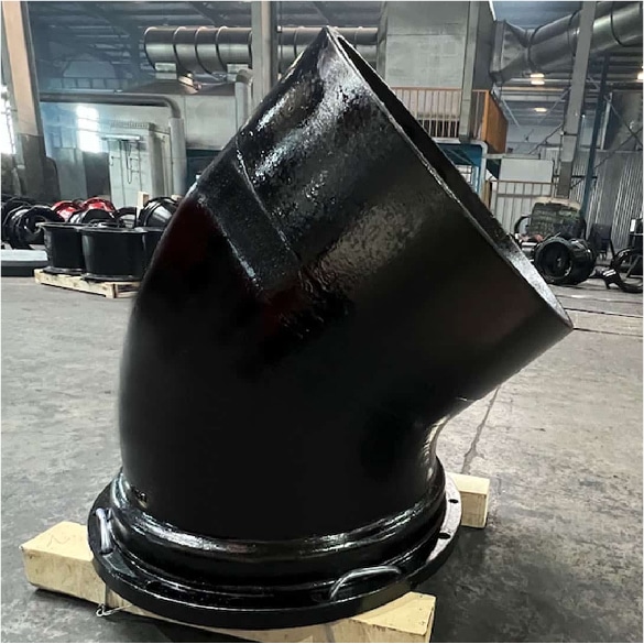
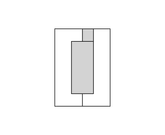
90℃ REDUCING BENDS
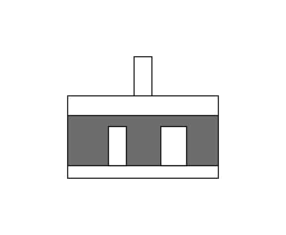
90° LONG RADIUS BEND
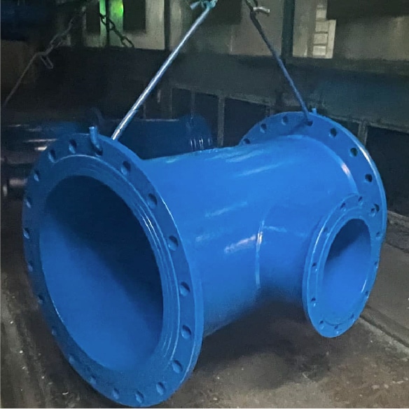
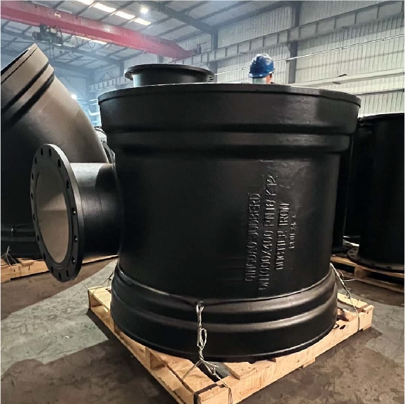
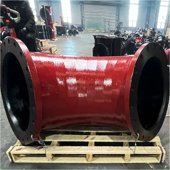
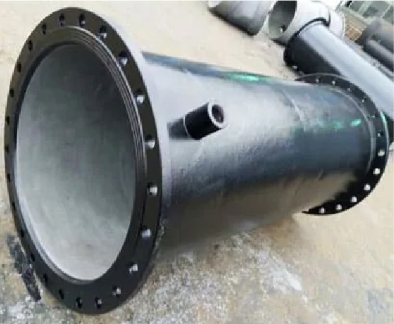
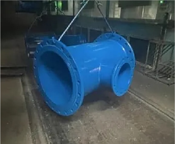
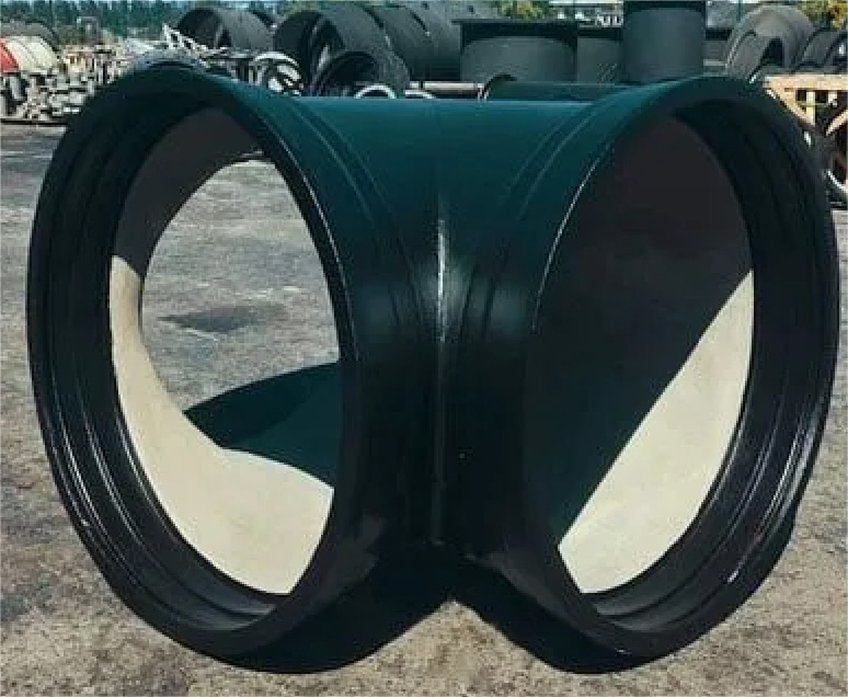
TEE
AWWA C153 DUCTILE IRON PIPE FITTING
Judberd can produce all ductile iron pipe fittings according to AWWA C153, include but not limit to below type, if you have enquiry sheet, welcome you contact judberd.
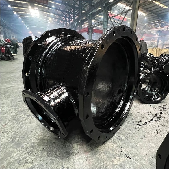
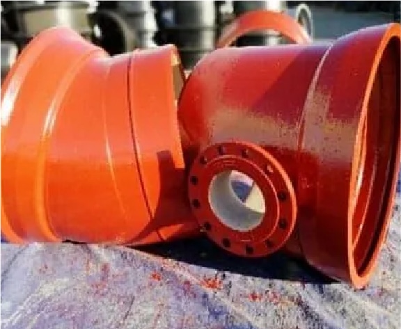
TEE
SLEEVE
REDUCER
BEND
BEND
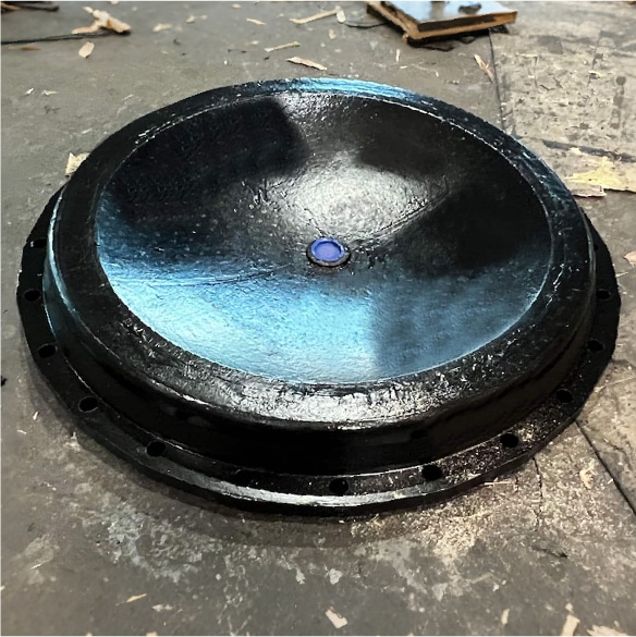
CAPS
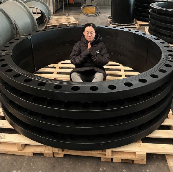
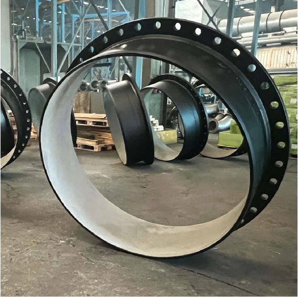
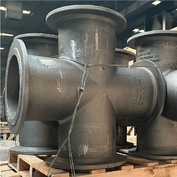
CUSTOM DUCTILE IRON PIPE FITTING
Judberd’s professional R&D team can design and customize pipe fittings based on your engineering requirements. Contact Judberd to get started on your custom design.
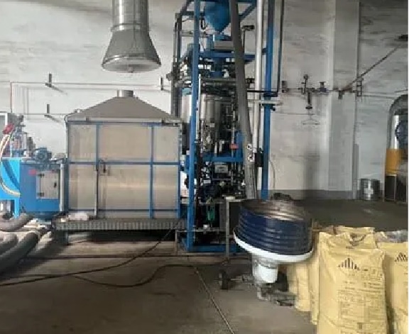
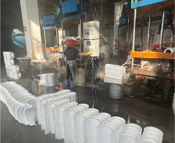
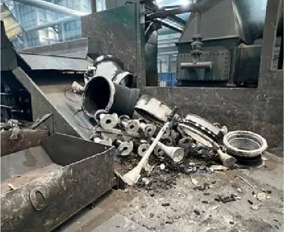
Judberd have 2 types production process, Vacuum lost foam casting and Static pressure line casting, their production processes are as below.
VACUUM LOST FOAM CASTING
Step 1 Preexpanding
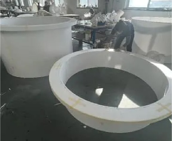
Step 2 Modelling for lost foam moulds
Step 3 Stick pieces together to shape the lost foam for casting
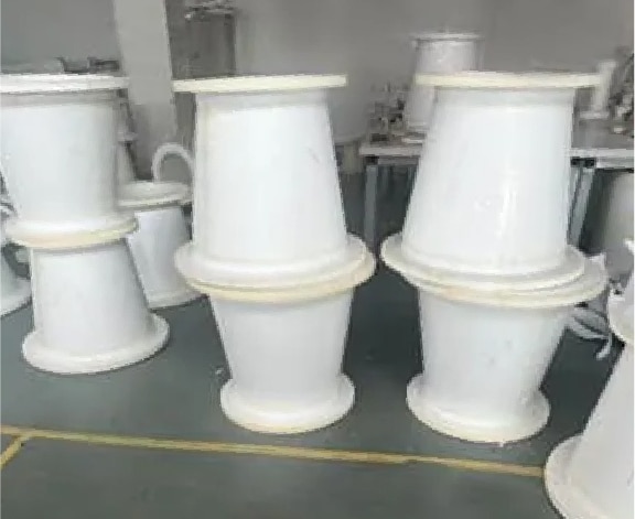
Step 4 Lost foam moulds are ready
Step 5 Coating for lost foam moulds
Step 6 Dry the coated lost foam moulds
Step 7 Put the lost foam in the casting box
Step 8 Assemble the pouring channel for the iron
Step 9 Cover lost foam moulds by sands
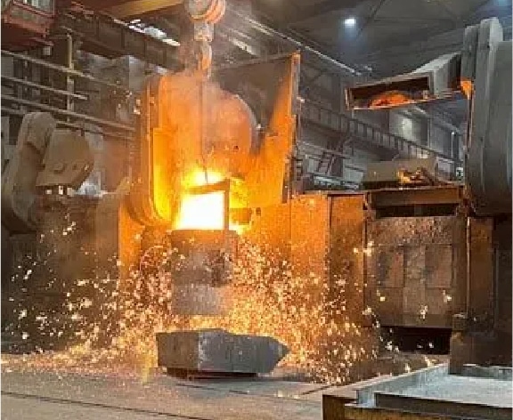
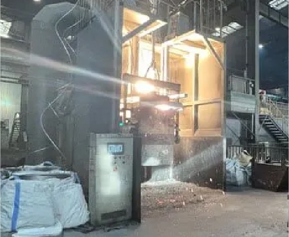
Step 10 Iron melting
Step 11 Nodular
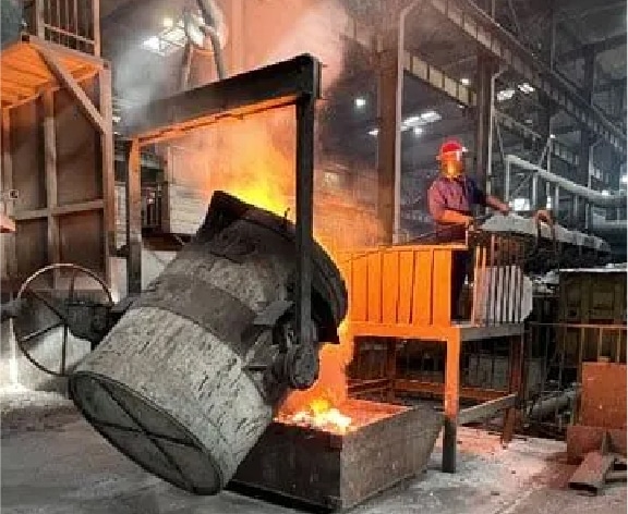
Step 12 Remove the slag from the molten iron
Step 13 Pouring
Step 14 Release of parts
Step 15 Polishing
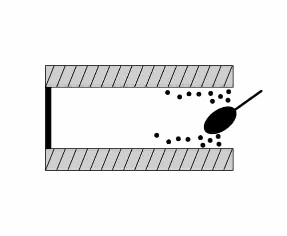
Step 16 Sand blast and machining
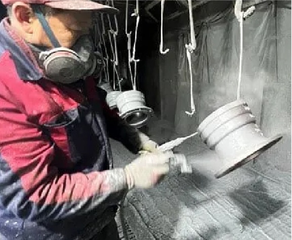
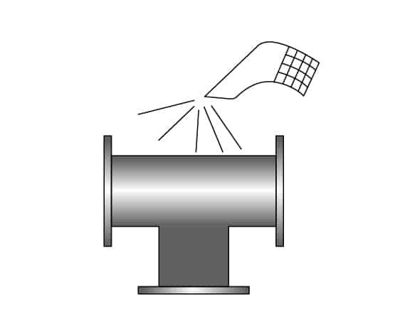
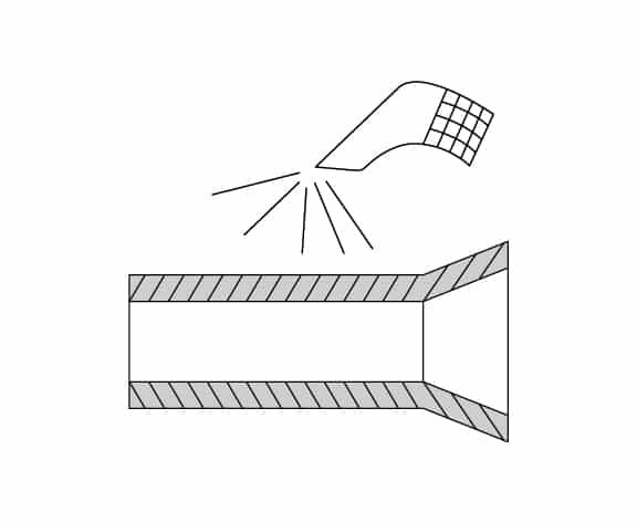
Step 17 Zinc spraying
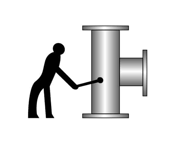
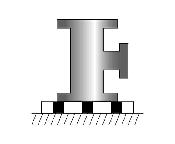
Step 18 Pressure test
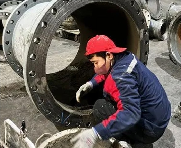
Step 19 Cement lining
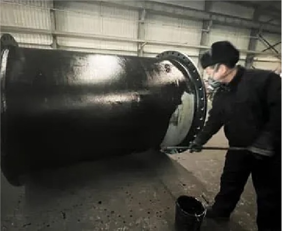
Step 20 Apply asphalt coating
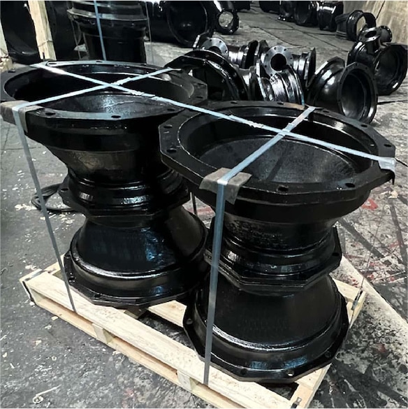
Step 21 Packing
After step 16 Sand blast and machining–FBE coating
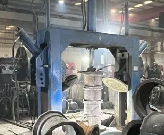
STATIC PRESSURE LINE CASTING
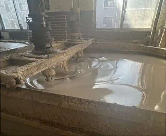
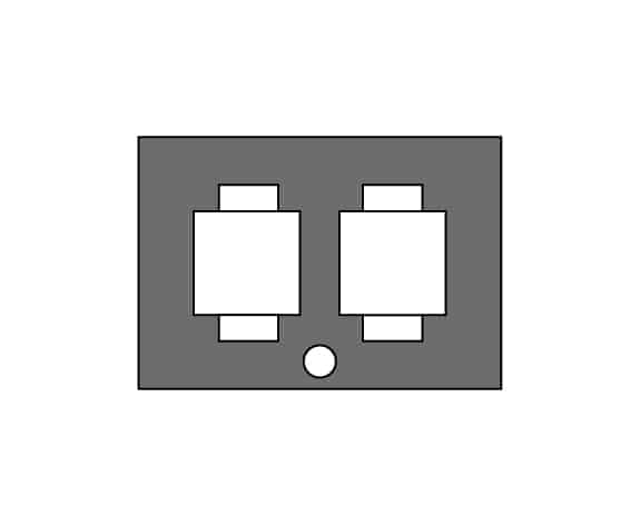
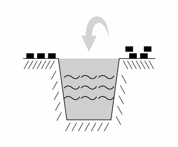
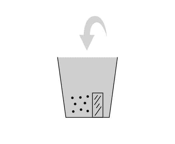
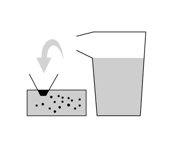
Step 1 Moulding sand preparation
Step 2 Injection molding
Step 3 Sand core preparation
Step 4 Bottom core closure
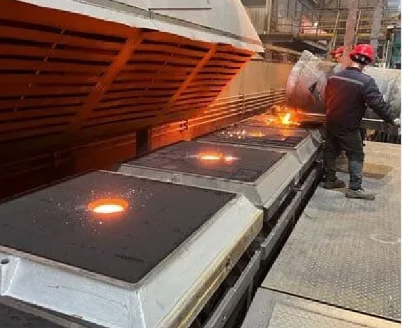
Step 5 Molten iron melting
Step 6 Nodular treatment
Step 7 Pouring
Step 8 Polish & Clean
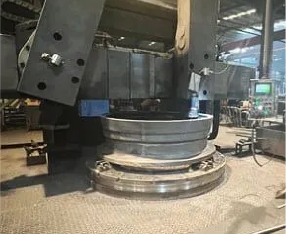
Step 9 Sand blast and machining
Step 10 Zinc paint spray
Step 11 Hydraulic pressure test
Step 12 Cement lining
Step 13 Bitumen paint externally
Step 14 Package
SURFACE COATING
We can do surface coating according to client project requirement, below several types are for your reference.
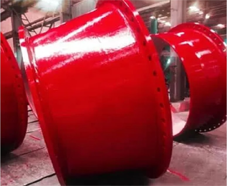
FOR POTABLE WATER
Cement inside,zinc and bitumen outside
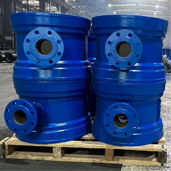
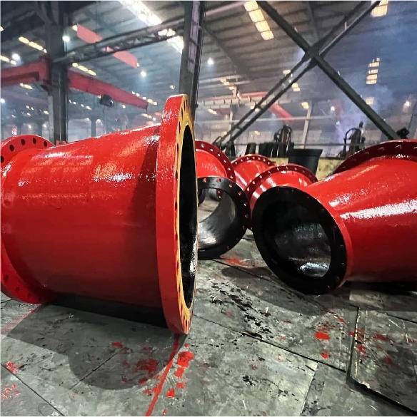
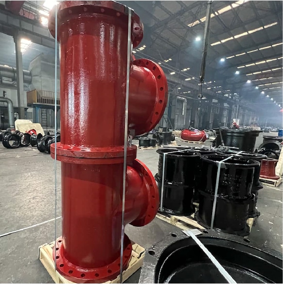
FOR SEWAGE
High alumina cement lining inside, red epoxy paint outside
FOR POTABLE WATER
Fusion bonded epoxy inside and outside
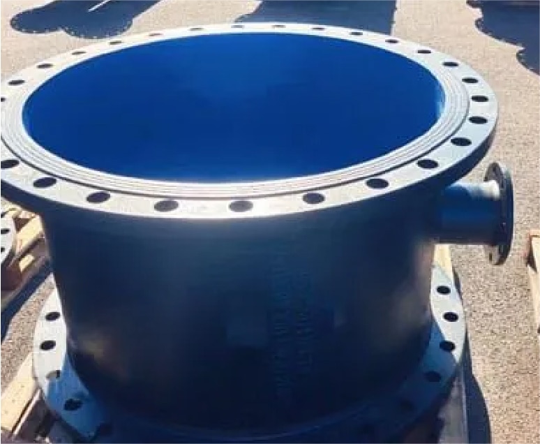
FOR POTABLE WATER
Epoxy paint inside, zinc and bitumen outside
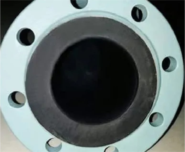
FOR SEA WATER
Epdm lining inside, anti-rust paint outside
FOR CHEMICAL FLUID
PTFE lining inside, red epoxy paint outside
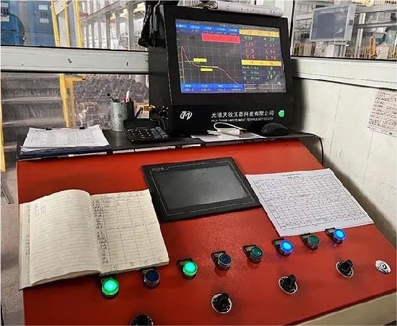
MATERIAL INSPECTION
1. Check the chemical composition of the iron with a pre-furnace analyser.
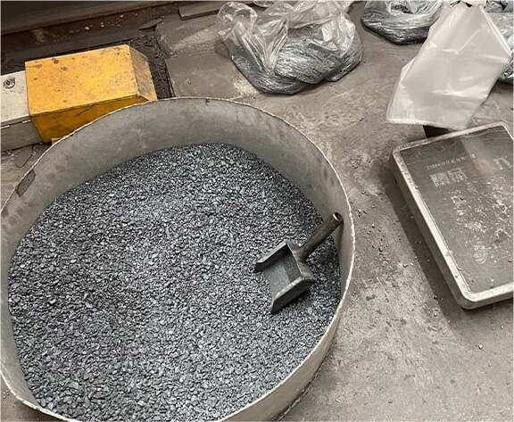
2. Adjust metal content in iron water by adding metal until the metal content is quanlified.
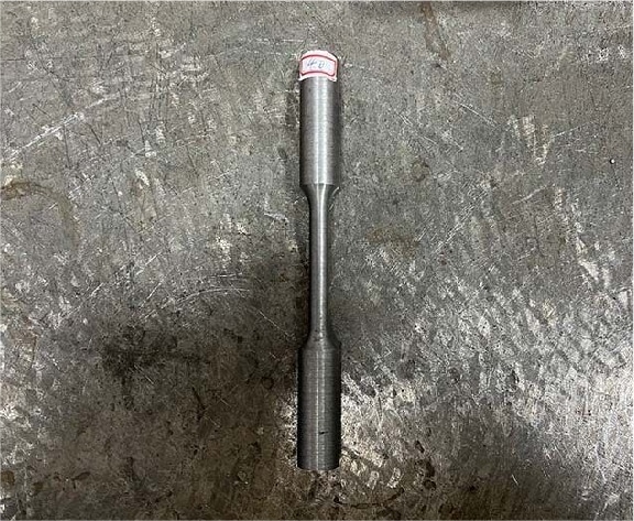
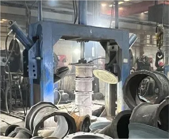
3. Machine test bars to standard sizes for tensile strength and elongation testing.
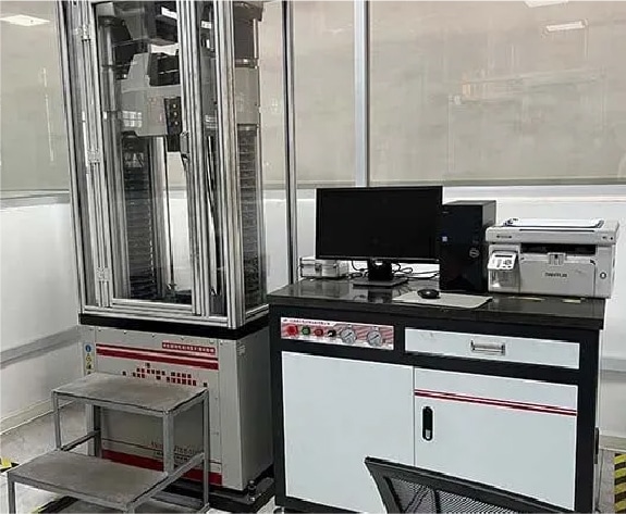
4. Use instrument to tensile test bars to test tensile strength and elongation.
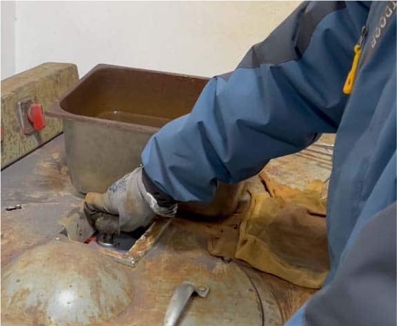
5. Polishing samples for spectroscopy with a spectroscopy grinder.
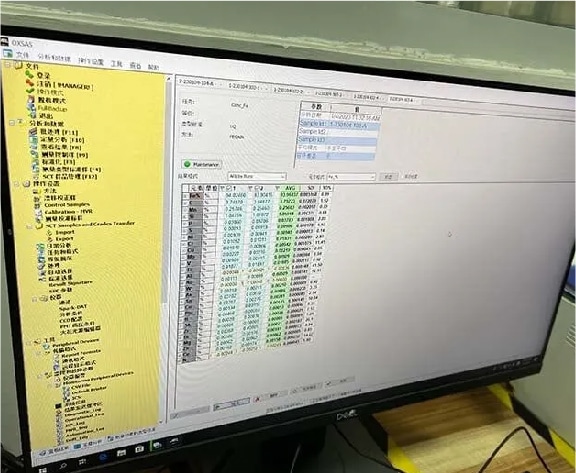
6. Chemical Composition Testing By Spectrometer, 2 Tests Are Required To Ensure Accuracy.
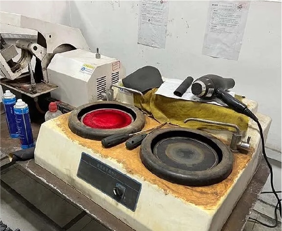
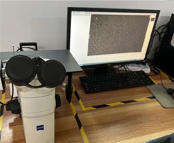
7. Polishing Of Samples For Metallographic Testing Using A Metallographic Specimen Grinding And Polishing Machine.
8. Metallographic testing to compare test results with standards to determine compliance.
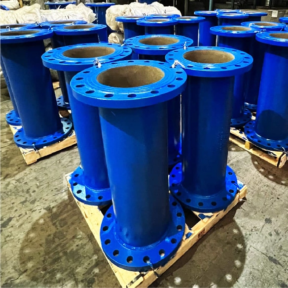
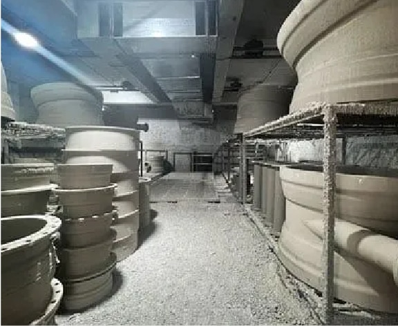
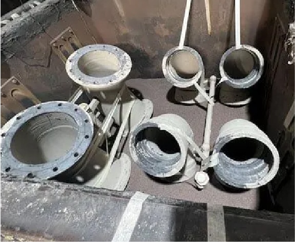
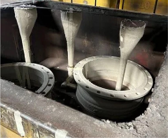
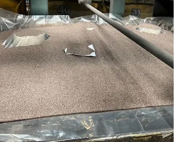
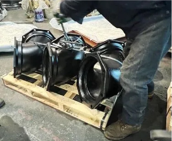
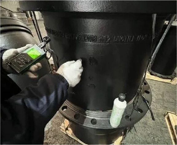
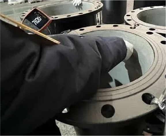
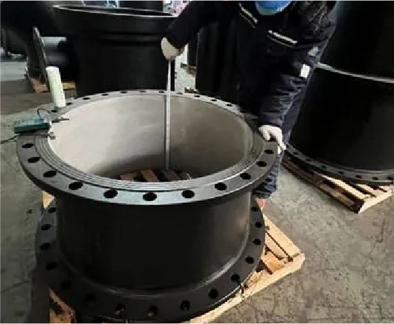
INSPECTION
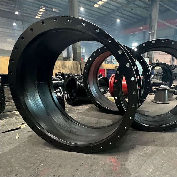
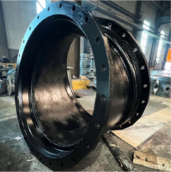
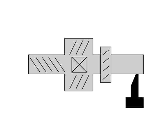
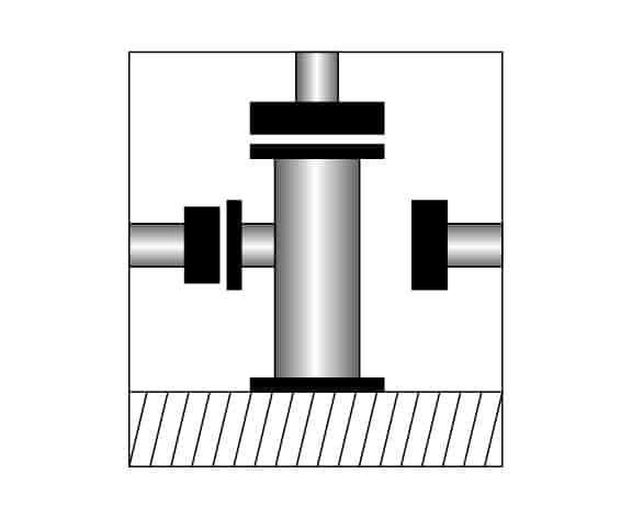
Judberd is a competitive manufacturer of ductile pipe fittings. We have strict inspection procedures for product quality , below photos are for your reference
Ductile iron pipe fittings are widely used for potable water, wastewater, and industrial applications, but different pipeline have different requirement for ductile iron pipe fitting, primarily in material selection, anti-corrosion coatings, connection methods, and pressure ratings.
1. POTABLE WATER SUPPLY
Applications Used in municipal water supply networks, water distribution pipelines, fire protection systems, and rural water supply.
Key Requirements is Material Safety, Must comply with drinking water safety standards such as ISO 2531, EN 545, AWWA C110/C153 to ensure no harmful substances are released.
● INTERNAL LINING (PREVENTS WATER CONTAMINATION)
Cement Mortar Lining – Commonly used, prevents water quality deterioration and provides some corrosion protection (ISO 4179).
Fusion Bonded Epoxy (FBE) Coating – Suitable for high-hygiene standard pipelines, offering superior corrosion resistance (AWWA C213, EN 14901).
● EXTERNAL PROTECTION COATING (CORROSION RESISTANCE IN VARIOUS ENVIRONMENTS)
Zinc Spray + Bitumen Paint – Basic protection (ISO 8179).
High-Performance Epoxy Coating – Suitable for highly corrosive environments such as coastal areas (AWWA C210, EN 545).
● PRESSURE RATINGS
Typically PN10, PN16, PN25, depending on water transmission pressure.
● CONNECTION METHODS
Socket Joint (Push-Fit Joint) – Common in municipal water networks, easy to install (EN 545).
Flange Joint – Used for large-diameter pipes or sections requiring disassembly and maintenance (ISO 7005).
2. WASTEWATER & SEWER SYSTEM
Applications Used in sewage networks, municipal drainage, and industrial wastewater treatment systems.
Key Requirements is Corrosion Resistance, Wastewater may contain acids, alkalis, and organic pollutants, requiring stronger anti-corrosion performance.
● INTERNAL LINING (CHEMICAL RESISTANCE)
Cement Mortar Lining – Suitable for general municipal sewage but has limited resistance to strong acids and alkalis (ISO 4179, EN 598).
High-Corrosion-Resistant Epoxy Coating – Used for industrial wastewater with chemical contaminants (AWWA C210, EN 14901).
Polyurethane Lining – Provides excellent abrasion resistance, suitable for wastewater containing sand, gravel, or particles (EN 15655).
● EXTERNAL PROTECTION COATING (CORROSION RESISTANCE IN VARIOUS ENVIRONMENTS)
Epoxy Powder Coating – Ideal for underground humid environments, enhances durability (AWWA C213, EN 598).
● PRESSURE RATINGS
Generally lower, typically PN6, PN10, PN16, as wastewater pipelines mainly rely on gravity flow and do not require high pressure.
● CONNECTION METHODS
Flexible Coupling – Recommended for areas with ground settlement, reducing pipeline stress.
Flange Joint – Used in pump stations and wastewater treatment plants requiring removable sections (ISO 7005).
3. INDUSTRIAL APPLICATIONS
Applications Used in industries such as oil, chemical processing, food manufacturing, metallurgy, and power plant cooling water systems.
Key Requirements is High-Temperature & Corrosion Resistance, Requires materials suited for chemical corrosion and high-temperature environments.
● INTERNAL LINING (FOR SPECIFIC MEDIA)
Rubber Lining – Ideal for strong acids and alkalis, used in chemical industries (ISO 1629).
Epoxy Coating – Suitable for industrial cooling water and general chemical transport (AWWA C210).
Ceramic Lining – Used for highly abrasive media such as slurry and mining applications.
PTFE (Polytetrafluoroethylene) Lining – Excellent chemical resistance, used for aggressive chemicals (ASTM D3307).
Hot-Dip Galvanized + Epoxy Coating – Suitable for high-humidity, high-salinity environments such as coastal industrial zones (ISO 1461).
PTFE Coating – Used for transporting organic solvents and highly corrosive chemicals (ASTM D3295).
● PRESSURE RATINGS
Industrial pipelines typically require higher pressure resistance, commonly PN16, PN25, PN40, or even higher depending on specific requirements.
● CONNECTION METHODS
Flange Joint – Ideal for high-pressure, high-temperature, and corrosive industrial pipelines (ISO 7005).
Threaded Joint – Suitable for small-diameter, high-pressure industrial piping.
The selection of ductile iron pipe fittings varies based on application needs.
For potable water, safety, hygiene, and pressure resistance are the primary concerns.
For wastewater, corrosion resistance and adaptability to chemical environments are critical.
For industrial applications, high-pressure and high-corrosion resistance requirements must be met with specialized linings and coatings.
CONNECTION METHODS
UNDERGROUND PIPING
CONNECTION METHODS
● Socket and Spigot Self-Anchoring Gasket Connection This connection uses the socket and spigot ends of the pipe fitting, with a rubber gasket to seal the joint. The self-anchoring function of the gasket helps prevent movement of the pipeline under external pressure. During installation, the pipe ends are inserted into the socket of the fitting, ensuring the gasket is properly placed and seated to create a tight seal.It is used for most underground piping, especially where a good seal is required and the ground is not likely to settle. It is great for piping that is fixed in place or under heavy soil pressure.
● Flanged Connection Flanged connections involve attaching a flange to each pipe end and bolting them together. A gasket is usually used between the flanges to ensure a leak-proof seal.It is used for underground piping or piping that requires periodic maintenance or disassembly. Especially good for high-pressure piping or piping that connects to valves, pumps, or other equipment.
ABOVE-GROUND PIPING
CONNECTION METHODS
● Flexible Coupling Connection Flexible couplings are used to connect pipes of different diameters or to compensate for slight misalignment or movement. The coupling wraps around the pipe joint with a flexible material (such as rubber or polyurethane) and is tightened with metal clamps, providing strong resistance to vibration and movement.It is used for above-ground piping that is subject to frequent vibration or slight movement, such as piping in industrial settings or under roadways where external forces may be present. It is also good for connecting pipes of different materials or sizes.
● Flanged Connection Like underground systems, flanged connections can be used for above-ground piping, especially in high-pressure systems or when you need to take it apart.It is used for above-ground piping systems, especially when you need to take it apart frequently for maintenance, inspection, or replacement.
UNSTABLE GROUND
CONNECTION METHODS
● Mechanical Joint Connection This method uses a metal joint and rubber gasket to connect the pipe ends. The pressure can be adjusted with bolts to ensure a tight seal. Mechanical joints can connect pipes of different sizes and materials, giving you flexibility in your piping system.It is used for areas with unstable ground, such as soft soil, areas that settle, or where there is seismic activity or vibration. The flexibility and ability to move with the ground make it perfect for these conditions.
● Socket and Spigot Self-Anchoring Gasket Connection When you are working in unstable ground, you must make sure the gasket is installed correctly to prevent leaks or the pipe from moving due to the ground. You may need extra support or a special design based on the ground conditions.It is used for areas with uneven ground or poor soil bearing capacity, particularly in soft or shifting soils.
SUMMARY OF CONNECTION METHODS FOR DIFFERENT ENVIRONMENTS
● Socket and Spigot Self-Anchoring Gasket Connection Use for underground piping, large installations, and permanent installations. It seals well and is great for high-pressure applications.
● Flanged Connection Use for above-ground piping or piping that you need to take apart frequently. Best for large diameter piping or high-pressure piping systems.
● Flexible Coupling Connection Use for above-ground piping, especially in places where vibration or slight misalignment is common.
● Mechanical Joint Connection Use for areas with unstable ground. It is flexible and resists movement, making it great for areas with seismic activity, settlement, or vibration.
Each connection method has its own unique advantages based on the installation environment. The right choice ensures the stability and safety of your piping system over time. Depending on the conditions where you are working, you need to choose the right connection method based on your use requirements, the conditions where you are working, and your maintenance needs.
COMMON ISSUES, POSSIBLE CAUSES,
AND SOLUTIONS FOR DUCTILE IRON PIPE FITTINGS
1. LEAKAGE AT THE JOINT
POSSIBLE CAUSES
● Improper Installation If the fittings are not installed correctly, the seals may not be tight enough, leading to leaks.
● Damaged Gaskets or Seals Gaskets or seals can wear out or get damaged during installation or because of environmental factors like excessive pressure or temperature.
● Incompatible Materials Using the wrong gasket material or pipe material for the specific application (e.g., oil, gas, or water) may cause sealing issues.
SOLUTIONS
● Check the Installation Make sure the pipe and fitting are lined up correctly and the gasket is seated properly in the groove. Tighten the bolts according to the manufacturer’s recommended torque settings.
● Inspect the Gasket Replace any damaged or worn gaskets with new ones that are compatible with the medium being transported (e.g., EPDM for water, NBR for oil).
● Material Compatibility Make sure the pipe, fitting, and gasket materials are suitable for the medium being transported and the environmental conditions.
2. CORROSION OF FITTING OR PIPE
POSSIBLE CAUSES
● Exposure to Harsh Environments Ductile iron fittings can corrode when exposed to certain chemicals, saltwater, or high humidity.
● Inadequate Coating or Surface Protection If the fittings are not properly coated or the coating wears off, they are more susceptible to corrosion.
SOLUTIONS
● Use Proper Coatings For outdoor or coastal installations, make sure the fittings are coated with anti-corrosion treatments like polyester FBE powder for UV resistance or epoxy coatings for moisture resistance.
● Regular Inspection Periodically check the fittings for signs of corrosion, especially in high-risk environments like marine or underground areas.
● Consider Material Upgrades If corrosion continues to be a problem, think about switching to stainless steel (e.g., SS304, SS316) or adding additional corrosion-resistant coatings to the fittings.
3. MISALIGNMENT OR UNEVEN STRESS ON THE FITTINGS
POSSIBLE CAUSES
● Incorrect Alignment During Installation When the pipes and fittings are not lined up correctly, uneven stress can be placed on the joints, leading to failure or deformation.
● Excessive Pressure Too much pressure in the pipeline can cause the fittings to deform, leading to leaks or damage.
SOLUTIONS
● Proper Alignment Make sure the pipe and fitting are lined up correctly before tightening. Use supports to hold the pipeline in place.
● Monitor Pressure Check the operating pressure of the pipeline and make sure it does not exceed the rated pressure of the pipe fittings. Consider using pressure regulators or pressure relief valves if needed.
● Install Expansion Joints For systems that experience temperature changes, installing expansion joints can help absorb the thermal expansion and prevent stress on the fittings.
4. CRACKING OR FRACTURING OF THE FITTINGS
POSSIBLE CAUSES
● Improper Handling During Installation Dropping or hitting the fittings during handling can cause cracks, especially if the fittings are not properly supported.
● Impact from External Forces External forces like heavy machinery or construction activities near the pipeline can result in cracking or fracturing.
● Excessive Temperature or Pressure Fluctuations Significant changes in temperature or pressure can cause the ductile iron to become brittle over time, leading to cracks.
SOLUTIONS
● Handle with Care Make sure the fittings are properly supported during handling and installation to avoid any impact damage.
● Protect from External Impact Install protective barriers or provide adequate clearance around the pipeline to prevent external impact or heavy machinery from damaging the fittings.
● Avoid Rapid Temperature/Pressure Changes Make sure the system operates within the recommended temperature and pressure limits to prevent thermal stress or pressure surges that could cause cracking.
5. DIFFICULTY TIGHTENING BOLTS OR FLANGES
POSSIBLE CAUSES
● Thread Damage or Corrosion on Bolts If the bolts or threads are corroded or damaged, it may be difficult to tighten the bolts properly.
● Improper Torque Settings If the bolts are not tightened to the manufacturer’s recommended torque, this can lead to either under-tightening (causing leaks) or over-tightening (causing damage).
SOLUTIONS
● Check Bolts for Damage Regularly inspect the bolts for signs of wear, corrosion, or damage. Replace any bolts that are not in good condition.
● Use Proper Torque Follow the manufacturer’s recommended torque settings for the bolts. Use a calibrated torque wrench to ensure accuracy.
● Lubricate Threads Apply anti-seize lubricant to the threads of bolts to prevent rusting and make the tightening process easier.
6. DEFORMATION OF FITTINGS DUE TO OVERLOADING
POSSIBLE CAUSES
● Excessive Load on the Pipeline Overloading the pipeline or fitting with too much weight or pressure can cause the fitting to deform or even fail.
● Improperly Sized Fittings If the fittings are not sized correctly for the pipeline’s pressure rating or the medium being transported, they may not be able to handle the load.
SOLUTIONS
● Choose Correctly Sized Fittings Make sure the fittings are sized correctly for the pipeline, taking into account factors like pressure rating and medium type.
● Avoid Overloading Do not exceed the pressure or load specifications for the system. If necessary, install pressure relief valves to prevent overloading.
7. UNEVEN FLOW OR PRESSURE LOSS
POSSIBLE CAUSES
● Improperly Sized Fittings or Pipes If the fittings or pipes are too small or too large for the application, it can cause flow restrictions or pressure loss.
● Internal Blockages Over time, debris or buildup inside the fittings can restrict the flow of fluid or gas, causing pressure loss.
SOLUTIONS
● Ensure Proper Sizing Confirm that the fittings and pipes are sized correctly for the intended flow rates and pressure. This may involve working with an engineer to verify the correct specifications.
● Regular Cleaning and Maintenance Clean the fittings and pipes regularly to prevent blockages or buildup that could restrict flow. This is especially important in systems that transport materials with high particulate content.
By understanding the common problems, possible causes, and appropriate solutions, you can take proactive steps to ensure the longevity and performance of your ductile iron pipe fittings. Regular inspections, proper installation, and choosing the right materials for specific conditions can help avoid most problems. If issues persist, it’s always a good idea to consult with judberd technician for further guidance.
Ductile fitting also called ductile pipe fitting, ductile iron fitting, ductile iron pipe fitting, DI pipe fittings or DI fittings. It is ductile iron material pipe fittings which normally be used for water supply. Compare to grey cast iron pipe fitting,Ductile iron pipe fittings have several advantages over grey cast iron pipe fittings, primarily due to their enhanced mechanical properties and performance characteristics. Here are the key advantages:
HIGHER STRENGTH AND DUCTILITY
DUCTILE IRON
Exhibits high tensile strength and significantly higher ductility due to its spherical graphite structure. This allows it to withstand greater internal pressures and external forces without fracturing.
GREY CAST IRON
Has lower tensile strength and limited ductility because of its flake-like graphite structure, making it more brittle and prone to cracking under stress.
IMPACT RESISTANCE
DUCTILE IRON
Better able to absorb and resist impact forces, reducing the risk of damage during handling, installation, and operation.
GREY CAST IRON
More susceptible to cracking and breaking under impact due to its brittle nature.
FLEXIBILITY
DUCTILE IRON
Offers greater flexibility, allowing it to bend slightly under stress without breaking. This property is crucial in applications where ground movement or thermal expansion may occur.
GREY CAST IRON
Rigid and less able to accommodate movement, increasing the risk of failure under dynamic conditions.
CORROSION RESISTANCE
DUCTILE IRON
Typically coated with protective layers such as epoxy, zinc, or bituminous coatings, enhancing its resistance to corrosion and extending its service life.
GREY CAST IRON
Can also be coated, but the inherent brittleness can lead to coating damage and subsequent corrosion over time.
LONGER SERVICE LIFE
DUCTILE IRON
Generally offers a longer service life due to its superior mechanical properties and resistance to environmental factors.service life due to its superior mechanic.
GREY CAST IRON
Shorter lifespan in comparison, particularly in demanding applications where mechanical stresses and environmental exposure are significant.
EASE OF INSTALLATION
DUCTILE IRON
Lighter and easier to handle compared to grey cast iron, facilitating quicker and more efficient installation.
GREY CAST IRON
Heavier and more cumbersome to work with, which can increase installation time and labor costs.
RESISTANCE TO FATIGUE
DUCTILE IRON
Better suited to withstand cyclic loads and fatigue, making it more reliable in applications with fluctuating pressures or loads.
GREY CAST IRON
More prone to fatigue failure due to its brittle nature.
DESIGN VERSATILITY
DUCTILE IRON
Can be cast into more complex shapes and thinner sections without compromising strength, providing greater design flexibility.
GREY CAST IRON
Limited by its brittle nature, which restricts the complexity of shapes and thinness of sections that can be cast.
COST-EFFECTIVENESS
DUCTILE IRON
While the initial material cost may be higher, the reduced maintenance, longer lifespan, and lower risk of failure often make ductile iron more cost-effective over the life of the installation.
GREY CAST IRON
Lower initial cost but may incur higher maintenance and replacement costs over time due to its brittleness and shorter service life.
Ductile iron pipe fittings offer superior strength, ductility, impact resistance, flexibility, and overall durability compared to grey cast iron pipe fittings. These advantages make ductile iron the preferred choice for many modern piping systems, particularly in applications requiring high performance and reliability.