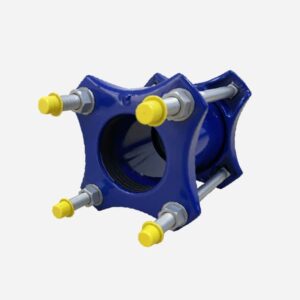
Mechanical Joint Coupling
A mechanical joint coupling is a type of pipe fitting used to connect two pipes, ensuring a secure, flexible, and leak-proof joint. This coupling type is commonly used in water and wastewater systems, fire protection systems, and various industrial applications. Its design facilitates easy assembly and disassembly, making it ideal for installations where flexibility and maintenance access are important.
Dedicated coupling for ductile iron pipe, steel pipe,AC pipe,GRP pipe,PVC pipe etc
● Dedicated coupling standard:comply with EN545
● Allows for minor deflection and axial movement, accommodating pipe misalignment and ground shifts.
● Can be used with various pipe materials including ductile iron, steel, PVC, and concrete.
● Coating standard:EN30677
● Test standard: EN12266-1
● Working pressure and Temperature
● size DN40 to DN2000,Working pressure PN10/PN16
● Temperature from -10℃ to 120℃ for EPDM gasket
● Temperature from -10℃ to 82℃ for NBR gasket
USe
● Connection for EN545/ISO2531 ductile iron pipe
● Angular deflection ±4℃
● WRAS,ACS,DVGW,NSF approved
Parts
END RINGS
_
metal rings that fits around the pipe, compressing the gasket to form a seal when bolts are tightened.
GASKET
_
A rubber or elastomer ring that provides the seal between the pipe and the coupling.
BOLTS AND NUTS
_
Used to tighten the end rings around the pipe, compressing the gasket and securing the connection.
MIDDLE SLEEVE
_
The main part of the coupling that houses the gasket and connects to the pipes.
Working Principle
installation
PREPARATION
_
Clean and prepare the pipe ends to ensure they are free of debris and damage.
ASSEMBLY
_
Slide the gasket over the pipe end, followed by the gland.
INSERTION
_
Insert the pipe end into the body of the coupling, ensuring it is properly seated against the internal stop.
tightening
Place the gland around the pipe and align it with the coupling body.
Insert the bolts through the flange holes of the gland and the coupling body.
Tighten the bolts evenly and progressively in a star pattern to ensure uniform compression of the gasket.
sealing
As the bolts are tightened, the gland compresses the gasket against the pipe and the coupling body.
The gasket expands to fill the gap between the pipe and the coupling, creating a watertight seal.
adjustment
The mechanical joint allows for slight angular deflection and axial movement, accommodating thermal expansion, contraction, and minor misalignments.
Application

WATER DISTRIBUTION SYSTEMS
Commonly used in municipal water supply networks for connecting pipes and fittings.
Suitable for underground installations where flexibility is required to accommodate ground movements.

WASTEWATER SYSTEMS
Used in sewage and drainage systems to ensure leak-proof connections in pipelines.
Ideal for applications where pipes may experience differential settlement or shifting.

FIRE PROTECTION SYSTEMS
Provides reliable connections in fire sprinkler and hydrant systems.
Ensures high integrity and leak-proof performance under pressure.

INDUSTRIAL PIPING SYSTEMS
Used in various industries for transporting liquids, gases, and chemicals.
Suitable for applications requiring frequent assembly and disassembly for maintenance.
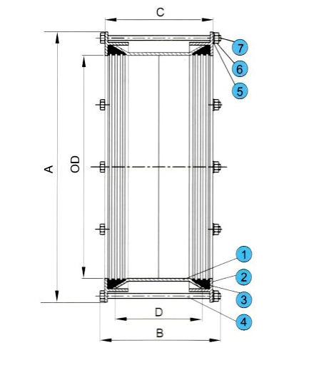
Drawing
Material specification
| Sr.No. | Name | Material |
|---|---|---|
| 1 | Center Sleeve | Carbon steel |
| 2 | End ring | Ductile iron |
| 3 | Gasket | EPDM |
| 4 | Bolt | Gal.steel |
| 5 | Washer | Gal.steel |
| 6 | Nut | Gal.steel |
| 7 | Cap | Plastic |
Options:Grade 4.8/6.8/8.8 carbon steel bolts with galvanization/dacromet/teflon etc
Stainless steel SS304/SS316/SS316L/A2/A4 etc bolts
FBE coating and Nylon 11 coating is available
Dimension
| Size | Pipe OD | A | B | C | D | Bolts No. |
|---|---|---|---|---|---|---|
| DN40 | 56 | 120 | 166 | 125 | 102 | 2 |
| DN50 | 66 | 126 | 166 | 125 | 102 | 2 |
| DN60 | 77 | 135 | 166 | 125 | 102 | 2 |
| DN65 | 82 | 156 | 166 | 125 | 102 | 2 |
| DN80 | 98 | 184 | 166 | 130 | 102 | 4 |
| DN100 | 118 | 205 | 166 | 130 | 102 | 4 |
| DN125 | 144 | 232 | 166 | 130 | 102 | 4 |
| DN150 | 170 | 264 | 173 | 133 | 102 | 4 |
| DN200 | 222 | 315 | 173 | 133 | 102 | 6 |
| DN250 | 274 | 374 | 173 | 136 | 102 | 6 |
| DN300 | 326 | 426 | 173 | 136 | 102 | 6 |
| DN350 | 378 | 494 | 254 | 200 | 152 | 8 |
| DN400 | 429 | 544 | 254 | 200 | 152 | 8 |
| DN450 | 480 | 595 | 254 | 200 | 152 | 10 |
| DN500 | 532 | 650 | 254 | 210 | 152 | 10 |
| DN600 | 635 | 753 | 254 | 210 | 152 | 12 |
| DN700 | 738 | 858 | 254 | 210 | 152 | 12 |
| DN800 | 842 | 962 | 254 | 210 | 152 | 12 |
| DN900 | 945 | 1070 | 280 | 238 | 178 | 14 |
| DN1000 | 1048 | 1173 | 280 | 238 | 178 | 14 |
| DN1100 | 1152 | 1282 | 280 | 240 | 178 | 16 |
| DN1200 | 1255 | 1385 | 280 | 240 | 178 | 18 |
| DN1400 | 1462 | 1592 | 295 | 250 | 178 | 20 |
| DN1600 | 1668 | 1798 | 295 | 250 | 178 | 24 |
| DN1800 | 1875 | 2015 | 375 | 320 | 254 | 32 |
| DN2000 | 2082 | 2222 | 375 | 320 | 254 | 36 |