Float Valve Manufacturer
Float valve is a device that controls water flow based on the level of the water. When the water level rises, the float closes the valve to stop the flow; when the water level drops, the float opens the valve to allow the flow. It works mechanically, without any power, and has a simple and reliable design.
Judberd is competitive manufacturer in china for float valve, our float valve include normal Remote control float valve, electric remote control float valve as below.
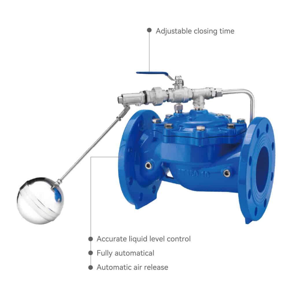
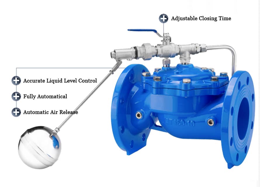
Normal Remote Control Float Valve
FEATURE
● Automatically controls the liquid level without the need for other devices or energy sources.
● High accuracy in liquid level control, unaffected by water pressure, with reliable sealing.
● Widely used for water level control in water towers, tanks, and similar facilities in high-rise buildings and residential water supply systems.
● Adjustable closing time.
● Precise level control.
● Automatic air release.
● Easy to install and maintain.
Closing time
≤ DN100(3-6S) DN125-200(4-8S) DN250-300(6-12S) DN350-800(12-30S)
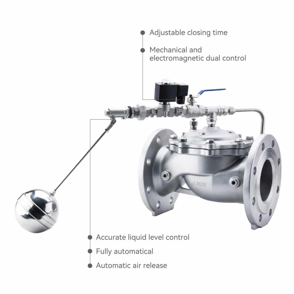
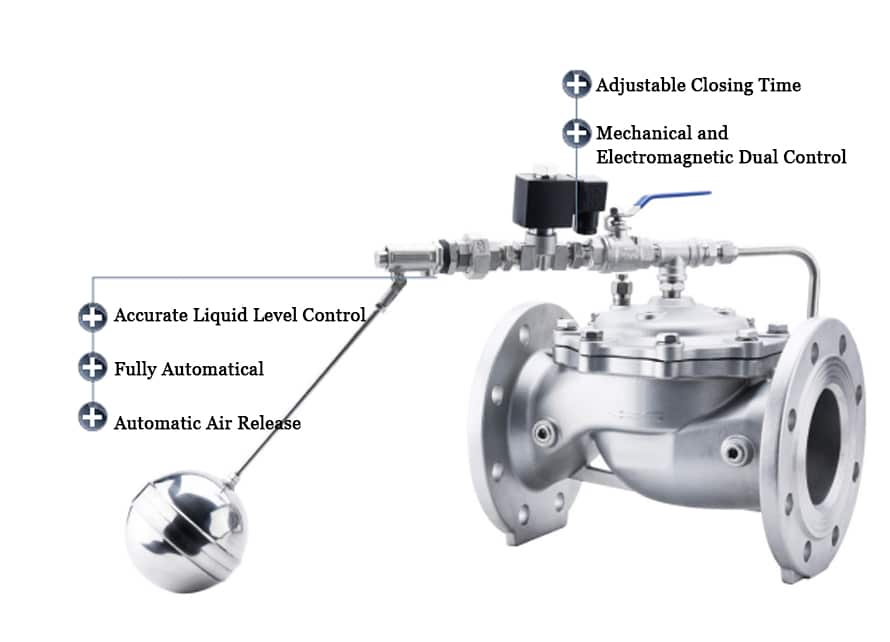
Electric Remote Control Float Valve
FEATURE
● Automatically adjusts capacity based on changes in supply and demand to maintain a constant liquid level.
● Dual control by mechanical and electromagnetic systems provides double safety protection.
● Adjustable closing time.
● Accurate liquid level control.
● Automatic air release.
● Easy to install and maintain.
Closing time
≤ DN100(3-6S) DN125-200(4-8S) DN250-300(6-12S) DN350-800(12-30S)
Parts & Working Principle
The remote float valve consists of a main valve, needle valve, ball valve, float pilot valve, and micro filter. Together, they make up a hydraulic control pipeline system that, once set, automatically controls the liquid level.
The remote float valve operates through hydraulic control to automatically control the liquid level.
When the level of the water in the tank or reservoir drops, the float drops, opening the float pilot valve.
This releases the pressure in the upper chamber of the main valve, allowing the main valve to open under inlet pressure and supply water to the tank.
As the water level rises to the preset height, the float rises and closes the pilot valve.
The upper chamber of the main valve is then pressurized again, forcing the main valve to close and stop the water supply.
The entire process operates automatically using hydraulic power—no external energy or manual control is required.
Types & Application
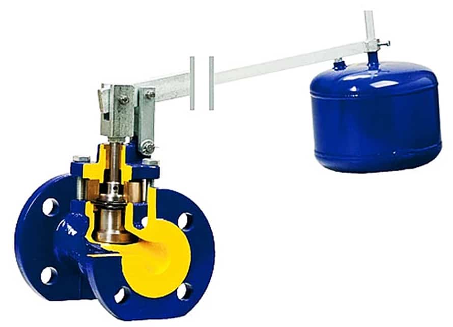
Mechanical Float Valve
Remote Float Valve
Electric / Solenoid Float Valve
Types and Differences of Float Valves
| Type | Control Method | Structure | Power Requirement | Maintenance | Response Speed |
|---|---|---|---|---|---|
| Mechanical Float Valve | Directly controlled by float arm | Simple mechanical design | No external power | Easy | Moderate |
| Remote Float Valve | Pilot valve controls main valve hydraulically | Main valve and float pilot are separated for remote control | No power required, water-powered | Moderate | Sensitive and accurate |
| Electric / Solenoid Float Valve | Controlled by electric signal or solenoid coil | Works with sensors or PLC for automatic operation | Requires electricity | More complex | Fast and precise |
Types & Application
Mechanical Float Valve
_
● Ideal for small water tanks, domestic water systems, and fire-fighting tanks.
● Simple structure, low cost, easy installation.
● Not suitable for high-pressure, large-flow, or long-distance control systems.
Remote Float Valve
_
● Suitable for medium to large water tanks, reservoirs, and high-rise water supply systems.
● The main valve is installed on the pipeline, while the float pilot is mounted at the liquid level, enabling remote hydraulic control.
● No power needed — perfect for areas without electricity or where safety is critical.
Electric / Solenoid Float Valve
_
● Ideal for smart water systems, industrial circulation water, and wastewater treatment plants.
● Provides precise level control, remote monitoring, and automatic operation.
● Requires electrical power and more complex maintenance.
Selection Guide
| Application | Recommended Type | Reason |
|---|---|---|
| Small or household water tanks, low budget | Mechanical Float Valve | Simple, economical, reliable |
| Medium-large tanks or water towers without power supply | Remote Float Valve | Hydraulic control, automatic operation, safe, stable |
| Industrial or automated systems requiring remote control | Electric / Solenoid Float Valve | Smart monitoring, high precision, fully automatic |
Summary
Mechanical Type
_
Simple, economical.
Remote Type
_
Hydraulic automatic control, safe, stable.
Electric Type
_
Intelligent control, high precision.
The key to selection lies in system size, power availability, control precision, and budget.
Float Valve Selection & Specifications
When selecting a float valve, key parameters such as working pressure, temperature, size, and body material should match the actual application conditions to ensure stable performance and long service life.
Working Pressure
_
● Standard working pressure: PN10–PN16 (10–16 bar)
● Optional: PN25 or higher for special high-pressure systems
● The valve should be rated at least 1.5× the system’s maximum operating pressure for safety.
Working Temperature
_
● Typical operating range: 0°C to 80°C
● For hot water or industrial use, select high-temperature models up to 120°C or above.
● The gasket and seal material (e.g., EPDM, NBR, PTFE) must be compatible with the medium temperature.
Nominal Diameter (Size Range)
_
● Common sizes: DN15 – DN300 (½” – 12″)
● For large reservoirs or municipal systems, valves can be customized up to DN600 or more.
Connection Types
_
● Threaded (BSP / NPT) – for small valves
● Flanged (EN1092 / ANSI / JIS) – for medium and large sizes
● Customized connections available upon request
Body Material Options
_
| Material | Features | Typical Applications |
|---|---|---|
| Cast Iron (GG25 / GGG40) | Economical, strong, suitable for general water supply | Domestic water tanks, irrigation |
| Ductile Iron (GGG50 / GGG60) | High strength, corrosion-resistant coating available | Municipal and industrial water systems |
| Brass / Bronze | Corrosion-resistant, compact, aesthetic | Small water tanks, household use |
| Stainless Steel (SS304 / SS316) | Excellent corrosion resistance, hygienic, durable | Drinking water, food-grade, seawater systems |
| Carbon Steel / Epoxy Coated | High-pressure and industrial use | Oil, gas, or cooling systems |
Selection Tips
01
Match pressure rating with pipeline pressure.
02
Choose material according to medium (freshwater, seawater, or chemical).
03
Confirm installation space and valve type (mechanical, remote, or electric).
04
Ensure seal material (EPDM/NBR) fits medium type and temperature.
Installation Guide for Float Valves
1. Mechanical Float Valve Installation
(Direct control by float arm)
Step 1: Preparation
_
● Clean the tank or pipeline connection point.
● Ensure the pipeline is flushed to remove debris or sand that may affect sealing.
Caution: Do not install near strong turbulence or water inlet jets, which may cause unstable float movement.
Step 2: Mounting the Valve
_
● Install the valve at the water inlet side of the tank using a threaded or flanged connection.
● The float arm should move freely up and down without obstruction.
Caution: Keep a proper clearance (at least 100 mm) around the float to avoid wall interference.
Step 3: Adjusting the Float Arm
_
● Adjust the float rod length or bend angle to set the desired water level.
● Tighten the locking nut to secure the arm position.
Caution: Over-tightening may damage the float arm threads; use moderate force.
Step 4: Testing
_
● Slowly open the water supply and check the valve’s open/close performance.
● Adjust the float height if the closing level is not accurate.
Caution: Do not allow sudden water pressure shocks during testing.
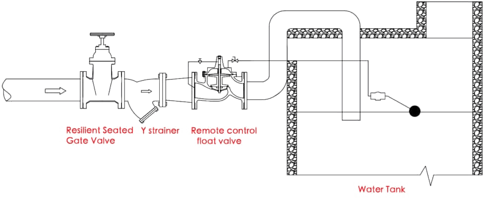
2. Remote Float Valve Installation
(Hydraulic control via pilot valve and main valve)
Attention:When installing a remote float valve, pay attention to the inlet flow direction — it must not be reversed. Before installation, the pipeline system must be thoroughly flushed and cleaned.
• A shut-off valve and filter should be installed before the remote float valve. The shut-off valve is usually placed upstream of the filter to make it easier to isolate the water source during maintenance.
• The pilot float valve must be installed above the liquid level in an easily accessible position for convenient maintenance.
• If the water surface is turbulent or wavy, the float should be installed inside a stilling well (with a diameter of not less than 200 mm) to ensure stable operation.
• The control pipeline connecting the main valve and the pilot float valve must have an inner diameter not smaller than that of the pilot valve’s port.
• The pilot float valve must be installed upright and level, not tilted.
Step 1: Preparation
_
● Confirm all components are complete: main valve, needle valve, ball valve, pilot float valve, filter, and tubing.
● Flush the pipeline before installation.
Caution: Any dirt in the control tubing may block the pilot system and cause malfunction.
Step 2: Main Valve Installation
_
● Install the main valve on the inlet pipeline in the horizontal position, with flow direction matching the arrow on the body.
Caution: Ensure sufficient straight pipe length before and after the valve (≥5×DN).
Step 3: Pilot Float Valve Installation
_
● Mount the float pilot valve at the desired liquid level position inside the tank.
● Connect the pilot valve to the main valve using copper or nylon control tubing according to the flow diagram.
Caution: Avoid sharp bends in the tubing; keep it fixed firmly to prevent vibration.
Step 4: Connection and Adjustment
_
● Open the needle valve slightly and adjust it to ensure smooth pressure response.
● Fill the tank and observe operation — the main valve should open when the water level drops and close when it rises.
Caution: If the valve reacts slowly, check for trapped air in control lines and release it.
Step 5: Final Check
_
● After confirming normal operation, lock all connections and secure tubing.
Caution: Regularly clean the micro-filter to prevent clogging.
3. Electric / Solenoid Float Valve Installation
(Electrical control system using level sensor or float switch)
Attention:When installing an electric remote float valve, pay attention to the inlet flow direction — it must not be reversed. Before installation, the pipeline system must be thoroughly flushed and cleaned.
• A shut-off valve and filter should be installed before the electric remote float valve. The shut-off valve is usually placed upstream of the filter to make it easier to cut off the water source during maintenance.
• The pilot float valve must be installed above the liquid level in an easily accessible position for convenient maintenance.
• If the water surface is turbulent or wavy, the float should be installed inside a stilling well (with a diameter of not less than 200 mm) to ensure stable operation.
• The control pipeline connecting the main valve and the pilot float valve must have an inner diameter not smaller than that of the pilot valve’s port.
• The pilot float valve must be installed upright and level, not tilted.
• The solenoid valve must have the correct voltage and the proper normally open or normally closed configuration.
Step 1: Electrical Preparation
_
● Verify power supply voltage (AC/DC) matches the solenoid coil rating.
● Confirm that the control panel or level sensor is properly grounded.
Caution: Electrical wiring must be done by qualified personnel to prevent short circuits.
Step 2: Valve Installation
_
● Install the valve on the inlet pipeline with the arrow matching the flow direction.
● Keep the solenoid coil in an upright position to ensure reliable operation.
Caution: Avoid installing in high-humidity or submerged environments unless waterproof type is used.
Step 3: Level Sensor Setup
_
● Mount the level sensor or float switch inside the tank at the desired liquid levels (high and low).
● Connect the sensor wires to the solenoid valve terminals as per wiring diagram.
Caution: Do not overextend sensor cables; fix them securely to prevent movement.
Step 4: Power-On Testing
_
● Turn on power and simulate level changes by manually moving the float switch.
● Observe if the solenoid valve opens and closes correctly.
Caution: If the valve buzzes or heats excessively, disconnect immediately and check the coil.
Step 5: Final Calibration
_
● Set control delays or sensitivity (if applicable) via the controller or PLC system.
● Conduct several full-level cycles to confirm stable performance.
Caution: Ensure power is cut off before maintenance or cleaning.
Summary Table
| Type | Installation Complexity | Key Caution | Typical Use |
|---|---|---|---|
| Mechanical | ★☆☆ Simple | Keep float movement unobstructed | Small water tanks |
| Remote | ★★☆ Medium | Prevent clogging or air in control line | Large tanks, towers |
| Electric / Solenoid | ★★★ Advanced | Electrical safety and proper grounding | Smart control systems |
Float Valve Troubleshooting
1. Why does the float valve leak or fail to close completely?
Possible Causes:
● Dirt or sand trapped in the valve seat or sealing surface.
● Damaged or aged rubber seal.
● Float arm angle misaligned, preventing full closure.
Solutions:
● Disassemble and clean the valve seat.
● Replace the seal if worn.
● Adjust the float arm position to ensure proper closing pressure.
2. Why is the float valve not opening when the water level drops?
Possible Causes:
● Float stuck or obstructed.
● Pilot valve blocked (for remote type).
● Solenoid coil failure (for electric type).
Solutions:
● Check if the float moves freely.
● Clean the pilot valve and tubing.
● Test the solenoid coil or electrical connection.
3. How to adjust the water level height?
Mechanical Type: Bend or adjust the float rod length to raise or lower the closing level.
Remote Type: Adjust the pilot float position or connecting rod height.
Electric Type: Modify the sensor or float switch position, or change setpoints on the controller.
Tip: Always test the system after adjustment to confirm accurate operation.
4. Why is water hammer or vibration occurring during operation?
Possible Causes:
● Valve closing too fast.
● Excessive inlet pressure fluctuation.
Solutions:
● Adjust the needle valve (for remote type) to slow down the closing speed.
● Install a pressure relief or surge tank if needed.
5. Why does the float valve make noise during operation?
Possible Causes:
● Air trapped inside the pipeline.
● Loose internal parts or unstable flow.
Solutions:
● Bleed the air from the system.
● Tighten internal fittings or add a damping device.
6. Why is the float arm or ball corroded or deformed?
Possible Causes:
● Aggressive medium (seawater, chemicals).
● Poor material selection.
Solutions:
● Replace with stainless steel or corrosion-resistant materials.
● Apply protective coatings if necessary.
7. How often should the float valve be maintained or cleaned?
Routine inspection: every 3–6 months.
Cleaning: remove sediment, scale, or rust buildup.
Seal replacement: every 1–2 years, or sooner if leakage appears.
Tip: Always shut off the water supply before maintenance.
8. How to clean or replace a float valve?
Steps:
● Close the upstream water supply.
● Disassemble the valve from the tank or pipe.
● Remove debris and check the seal and seat.
● Replace damaged parts or seals.
● Reinstall and test for leakage.
Caution:
Do not use sharp tools that may scratch the sealing surface.
9. Why is the valve responding slowly to water level changes?
Possible Causes:
● Pilot or needle valve partially blocked.
● Control tubing too long or contains trapped air.
Solutions:
● Clean or replace the pilot valve.
● Shorten the tubing and remove air pockets.
10. Why does the electric or solenoid float valve fail to energize?
Possible Causes:
● Power supply failure or wrong voltage.
● Coil burnt out or controller malfunction.
Solutions:
● Check power source and wiring.
● Measure coil resistance; replace if open.
● Inspect the control relay or PLC signal output.
Maintenance Tips Summary
| Task | Frequency | Notes |
|---|---|---|
| Visual inspection | Monthly | Check for leaks or corrosion |
| Cleaning filter & valve seat | Every 3–6 months | Keep control tubing clean |
| Seal replacement | 1–2 years | Use original or compatible material |
| Float calibration | As needed | Re-adjust after maintenance |
| Full functional test | After any repair | Verify open/close timing |
