Pressure Relief, Sustaining, or Back Pressure Control Valve
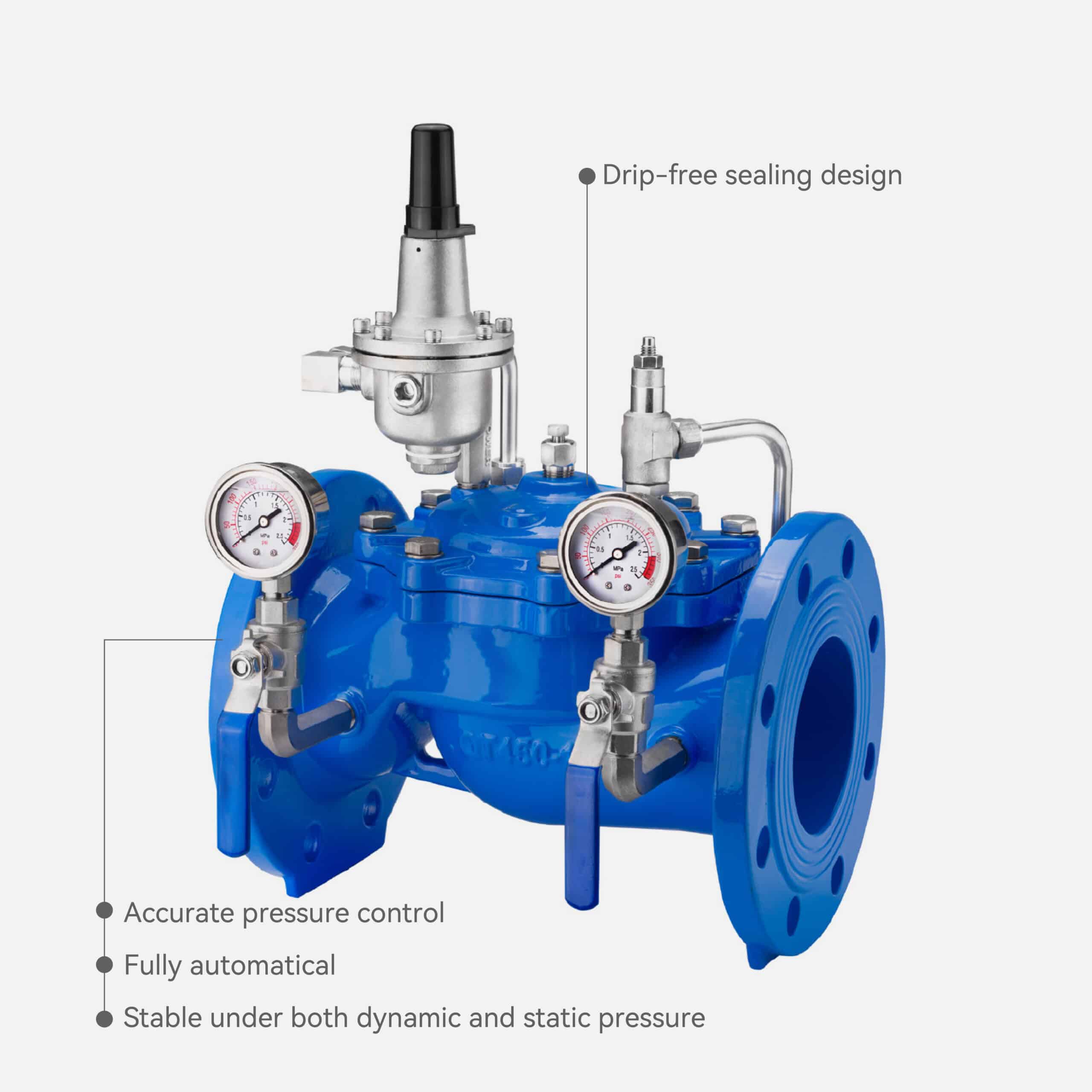
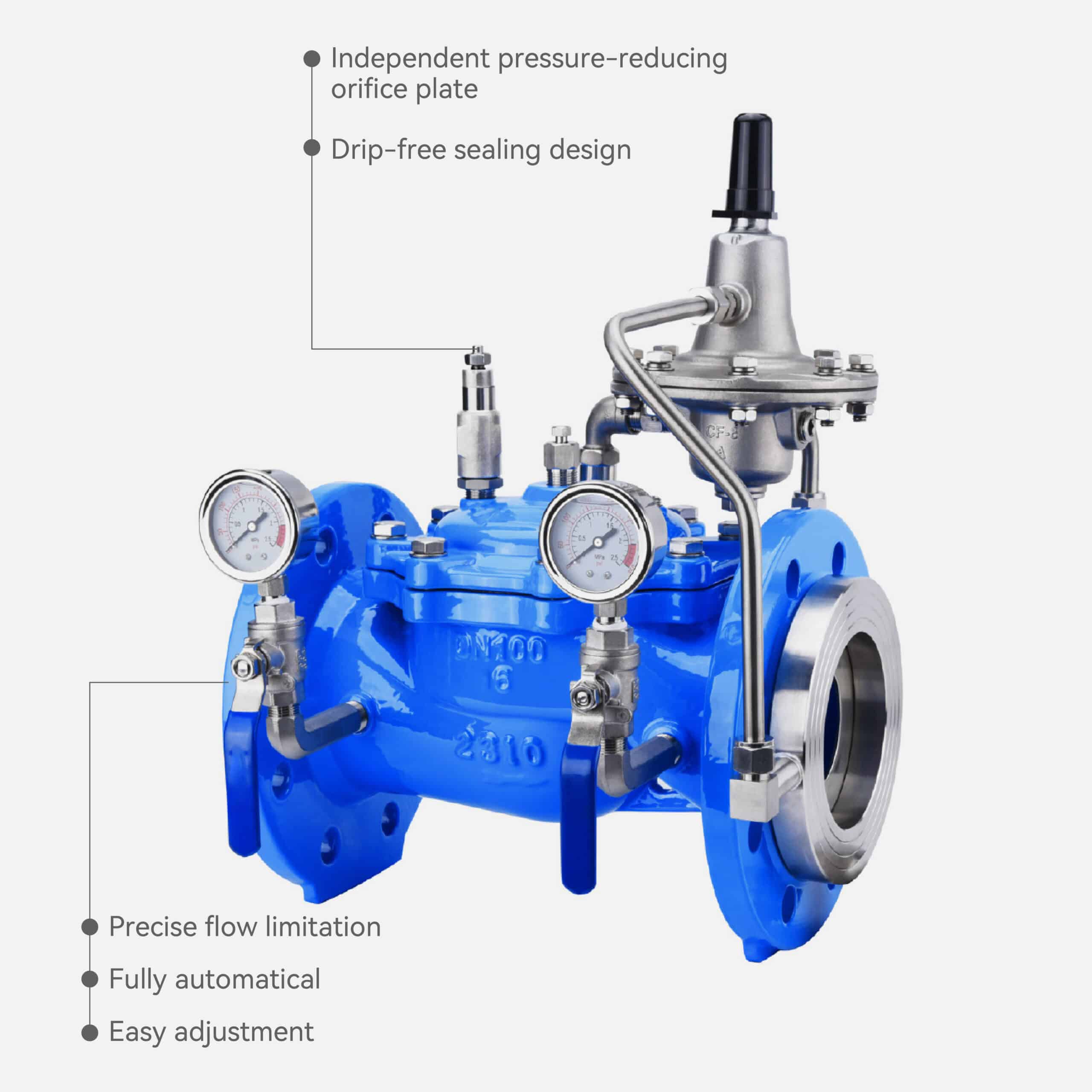
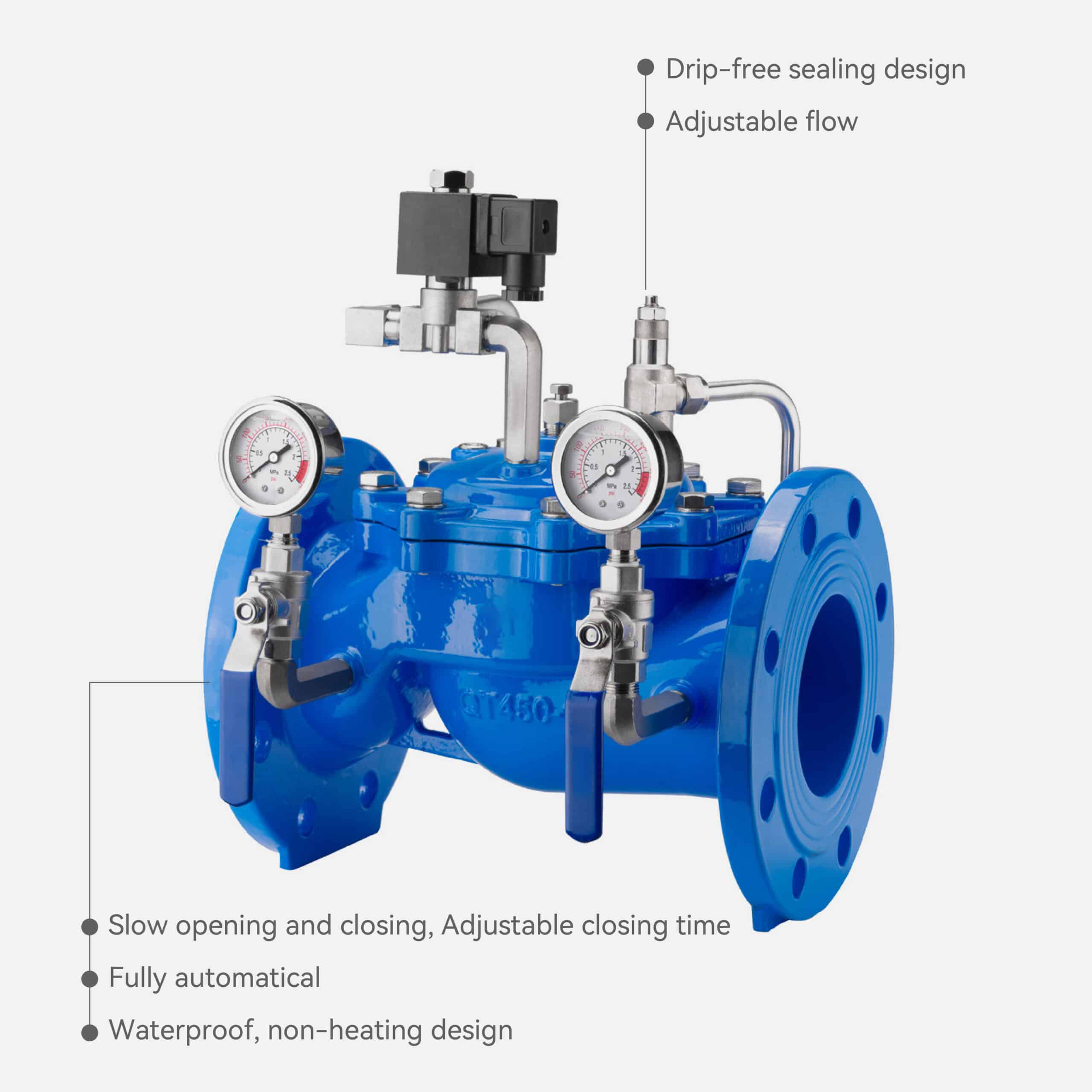
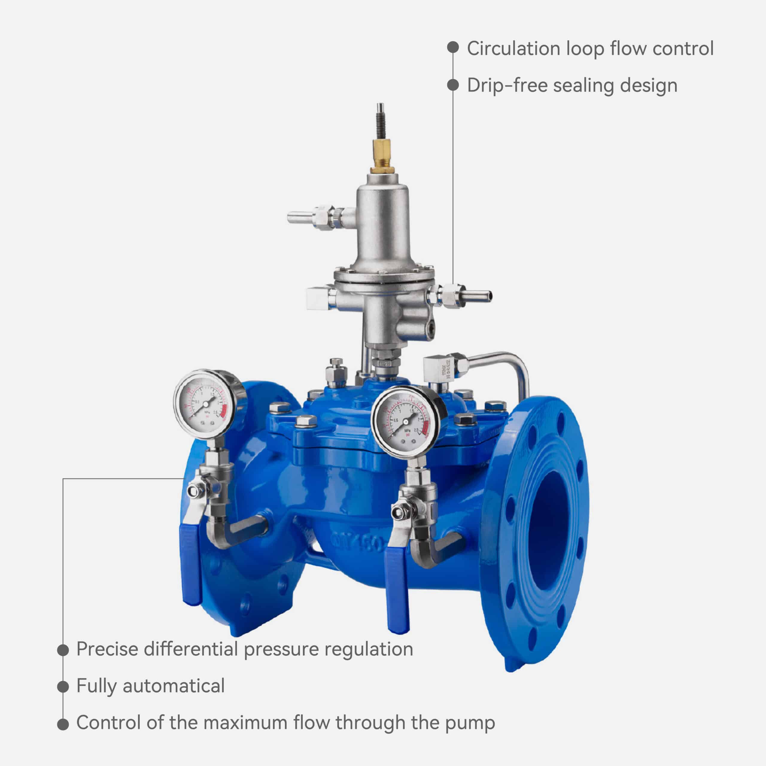
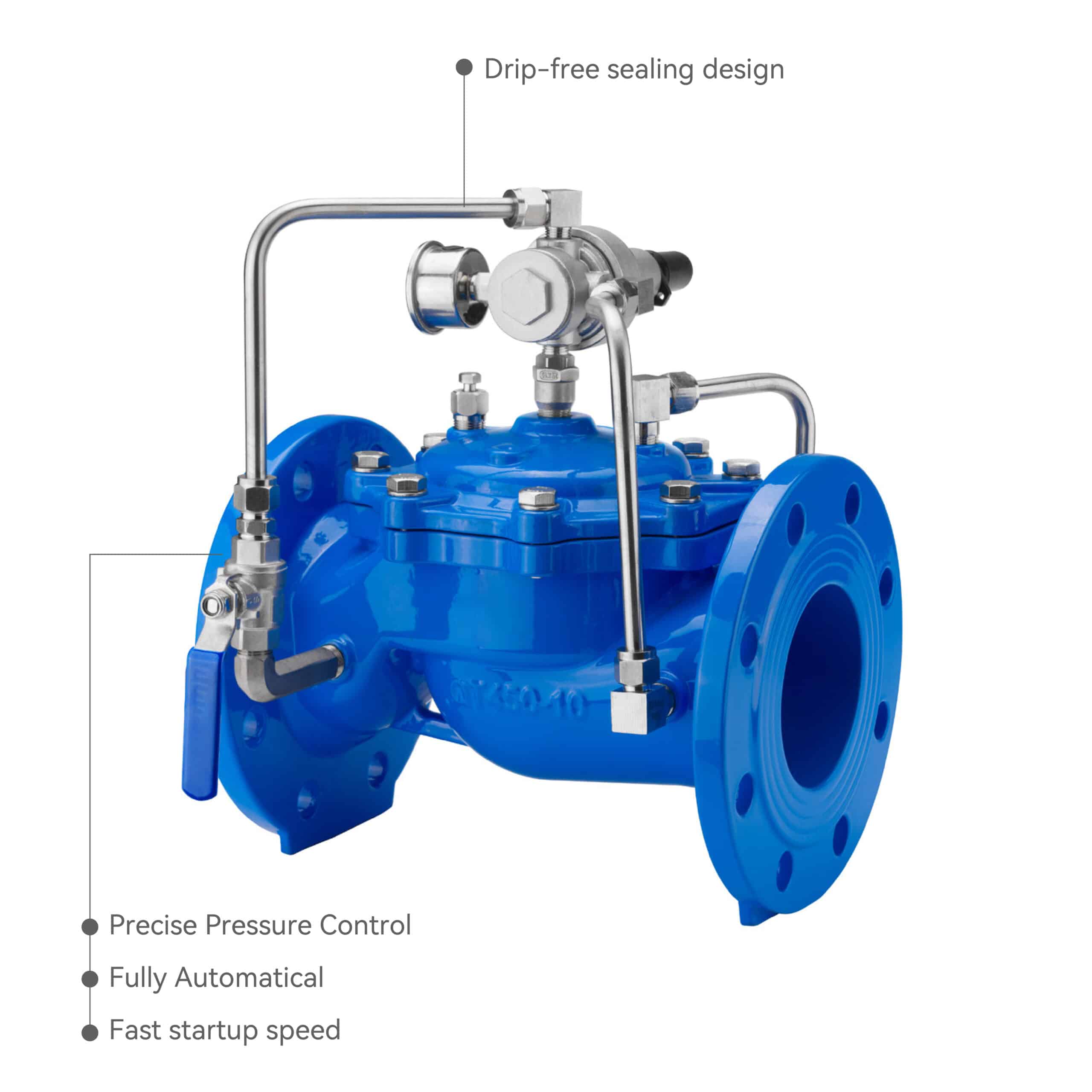
The Pressure Relief & Sustaining Valve is a hydraulically operated, pilot controlled, diaphragm valve.
It operates automatically by water pressure without the need for external power.
It consists of a main valve, relief/sustaining pilot valve, needle valve, ball valves, micro strainer, pressure gauge, forming a complete hydraulic control circuit.
Depending on the pilot valve adjustment, it functions as:
Pressure Relief Mode – opens automatically when system pressure exceeds the preset value, discharging excess pressure.
Pressure Sustaining Mode – closes automatically when upstream pressure drops below the set value, maintaining a stable supply pressure.
Feature
Nominal Diameter: DN40–DN800
Sealing Material: EPDM or NBR
Applicable Temperature: ≤ 80℃
Applicable Medium: Clean Water
Body Material: Ductile Iron, Brass, 304/316 Stainless Steel
Set Pressure:
PN10 (0.2–0.9 MPa)
PN16 (0.2–1.5 MPa)
PN25 (0.2–2.1 MPa)
Precise Pressure Control
Fully Automatical
Fast Startup Speed
angle type design
Selection Guide
To select the correct pressure relief and sustaining valve, you need to consider the type of system, the working pressure, the characteristics of the fluid, the temperature range, the nominal diameter (DN), and the flow requirements.
If you select the right valve, you will have a stable system, a long service life, and a valve that is easy to maintain.
Overview of the Selection Logic
A pressure relief and sustaining valve has two functions.
It can protect you from overpressure (relief) and it can stabilize the pressure upstream (sustaining).
Different systems emphasize different functions:
01
Water supply system → pressure stabilization & overpressure protection
02
Pumping station → prevent surges during start/stop
03
Fire protection system → avoid excessive system pressure
04
Industrial or irrigation system → maintain constant process pressure
Step-by-Step Selection Processc
| Step | Selection Item | Description | Typical Reference |
|---|---|---|---|
| 1️Define the Function | Relief / Sustaining | Identify the main function: | Dual-function is common in water supply |
| • Relief: opens when system pressure exceeds set value | |||
| • Sustaining: maintains upstream pressure above set value | |||
| 2️Determine Nominal Diameter (DN) | DN15–DN600 | Match the valve size to the pipeline diameter | DN25–DN300 most common |
| 3️Identify Inlet Pressure (P₁) | Maximum system pressure | Based on pump discharge or upstream main pressure | 0.4–1.6 MPa typical |
| 4️Set Outlet Pressure (P₂) | Desired control pressure | Usually 50–90% of inlet pressure | e.g. P₁=1.0MPa → P₂=0.6MPa |
| 5️Verify Max Working Pressure | Pressure rating of valve | Should be ≥ 1.25× system max pressure | PN10 / PN16 / PN25 |
| 6️Define Medium Type | Water, seawater, oil, etc. | Choose materials & seals accordingly | See table below |
| 7️Check Operating Temperature | ℃ | Determines sealing material | ≤85℃ for water, ≤120℃ for process fluids |
| 8️Evaluate Flow Characteristics | Flow–pressure curve | Ensure valve Kv (Cv) matches system flow | Calculated by system design |
| 9️Choose Valve Material | Ductile iron / Stainless steel / Brass | Based on pressure, medium, and corrosion level | See recommendations below |
| 10️Confirm Connection Type | Flanged / Threaded / Grooved | Match system connection type | Flanged for DN≥50 |
Typical Selection Examples by Application
| Application | System Characteristics | Recommended Configuration | Notes |
|---|---|---|---|
| Municipal Water Supply | Clean water ≤1.6 MPa | Body: Ductile iron | Cost-effective, WRAS/ACS certified options |
| Coating: Epoxy powder | |||
| Seal: EPDM | |||
| Fire Protection Network | High pressure fluctuation, surge risk | Body: Ductile iron / Carbon steel | Fast response, anti-water-hammer design |
| Pilot: Stainless steel | |||
| Seal: EPDM | |||
| Pumping Station Outlet | Frequent pressure variation | Body: Carbon steel / Stainless steel | Dual function—relief & sustaining |
| Pilot: Adjustable type | |||
| High-Rise Building Supply | Large pressure difference | Body: Ductile iron | Maintains upper-zone pressure, prevents overpressure in lower zones |
| Seal: EPDM | |||
| Pilot: Brass | |||
| Industrial Cooling or Process Water | May contain particles or mild chemicals | Body: Stainless steel 304/316 | Corrosion and temperature resistant |
| Seal: NBR/PTFE | |||
| Irrigation & Water Treatment | Unstable water quality, temperature change | Body: Ductile iron / Stainless steel | Anti-clog design, reliable operation |
| Lining: Epoxy / Rubber | |||
| Seal: EPDM |
Technical Reference Table
| Parameter | Recommended Range | Description |
|---|---|---|
| Nominal Diameter (DN) | DN15–DN600 | Pipeline size |
| Nominal Pressure (PN) | PN10 / PN16 / PN25 | Pressure rating |
| Inlet Pressure Range | 0.2–1.6 MPa | Working inlet pressure |
| Set Pressure Range | 0.05–1.2 MPa | Adjustable control pressure |
| Medium | Water, seawater, oil, aqueous solution | Applicable fluids |
| Operating Temperature | 0–85 °C (up to 120 °C optional) | Working temperature |
| Flow Characteristic Deviation | ±5 % | Flow accuracy |
| Pressure Characteristic Deviation | ±10 % | Pressure accuracy |
| Connection Type | Flanged / Threaded / Grooved | Installation method |
| Control Type | Pilot-operated hydraulic | Operation mode |
Recommended Materials & Sealing Options
| Environment | Body Material | Pilot Material | Seal Material | Coating / Surface Treatment |
|---|---|---|---|---|
| General Water | Ductile iron EN-GJS-450-10 | Brass / Stainless steel | EPDM | Epoxy powder coating |
| Corrosive or Seawater | Stainless steel 316 / 316L | Stainless steel | EPDM / FKM | Electropolished / corrosion-resistant |
| Oil or Hydrocarbon Medium | Carbon steel / Stainless steel | Stainless steel | NBR | Painted or galvanized |
| High-Temperature Fluid | Stainless steel / Bronze | Stainless steel | PTFE / FKM | Heat-resistant finish |
| Drinking Water (Certified) | Ductile iron + Epoxy | Brass / Stainless steel | EPDM (WRAS approved) | Epoxy or Nylon 11 coating |
Quick Selection Summary
Step 1
_
Identify the application and function
Step 2
_
Define inlet/outlet pressures and flow
Step 3
_
Choose DN and connection type
Step 4
_
Select materials and sealing based on medium
Step 5
_
Confirm certifications and installation orientation
Selection Data Sheet (for inquiry)
_
● Nominal Diameter (DN): _____
● Inlet Pressure (P₁): _____ MPa
● Set Pressure (P₂): _____ MPa
● Working Medium: _____
● Temperature: _____ °C
● Connection Type: Flanged / Threaded / Other
● Certification Required (WRAS / NSF / DVGW): Yes / No
A correctly selected pressure relief and sustaining valve will automatically release excess pressure while maintaining upstream stability, ensuring safe and reliable system operation.
By following the steps above, engineers can quickly determine the right model for any water, fire-fighting, industrial, or irrigation system.
Installation & Adjustment Guide
Installation Requirements
The pressure relief and sustaining valve can be installed vertically or horizontally, depending on site conditions.
Ensure that the flow direction strictly follows the arrow marked on the valve body — reversed installation is not allowed.
If the valve is installed inside a chamber or underground pit, make sure there is sufficient space around the valve for lifting, inspection, and maintenance.
Pre-Installation Preparation
Step Description
Step 1
_
Flush and clean the entire pipeline thoroughly to remove debris, sand, and welding residues. Contaminants can block the pilot control system.
Step 3
_
Inspect the valve internally and externally to ensure the pilot tubing and ports are clean and unobstructed.
Step 3
_
Check the body, flanges, and sealing surfaces for damage or deformation.
Step 3
_
Confirm that the working pressure, flow direction, and connection size match the design requirements before installation.
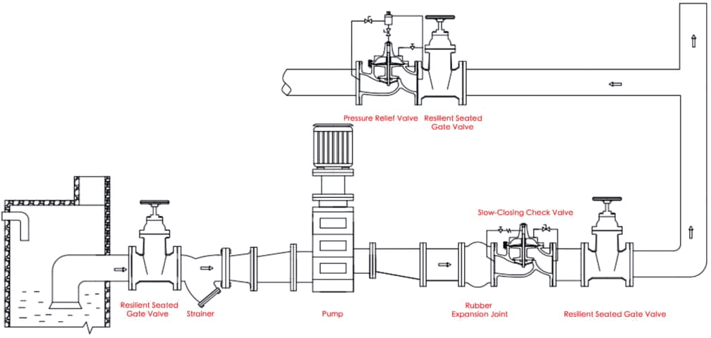
Recommended Piping Layout
To ensure reliable operation and easy maintenance, the valve should be installed with the following upstream and downstream components:
Upstream Arrangement
Shut-off valve
_
installed before the strainer, allowing water supply to be isolated for maintenance.
Strainer
_
prevents debris from entering the pilot system and ensures responsive control.
Pressure Relief & Sustaining Valve
Downstream Arrangement
Rubber expansion joint or flexible connector to absorb water hammer and vibration.
If other valves are connected downstream, leave sufficient spacing for maintenance access.
Auxiliary Components
The pilot control circuit should include needle valves and ball valves for adjusting flow and isolating the pilot line during maintenance.
Ensure adequate clearance for operating the ball valve handles and needle valve handwheels.
Orientation & Position
Point Description
Flow Direction
_
Must follow the arrow cast on the valve body. Reversed installation is not allowed.
Mounting Orientation
_
Can be installed vertically or horizontally. In horizontal installations, the valve bonnet must face upward.
Space Requirement
_
Provide sufficient clearance around the valve for maintenance or lifting, especially when installed in a valve chamber.
Pressure Testing & Adjustment Procedure
01
Before filling the system, make sure all valves — including the pilot-line ball valves — are fully open.
02
Fill the system slowly to prevent pressure surges or unintended pilot activation.
03
When the system reaches normal pressure, adjust the pilot valve set screw:
● Turn clockwise → increase the set pressure
● Turn counter-clockwise → decrease the set pressure
04
After adjustment, tighten the locknut and record the final set value.
05
Check that the main valve operates smoothly — no vibration, no chattering, and no leakage.
06
After pressure testing, re-inspect all pipeline connections and pilot tubing for tightness.
Important Notes
Do not use this valve as the main isolation (shut-off) valve.
Never perform pressure testing before the pipeline has been completely flushed.
If the valve will remain idle for a long time, close the pilot ball valves and drain all residual water.
Inspect the pilot valve and needle valve every 6 months to ensure smooth operation and sensitivity.
Avoid prolonged exposure to standing water or direct sunlight to protect the external coating and extend service life.
Recommended Installation Schematic (Text Description)
Flow direction: →Inlet → Shut-off Valve → Strainer → Pressure Relief & Sustaining Valve → Flexible Joint → Outlet
Pilot control circuit includes:Needle valve, ball valves, micro strainer, and pressure gauge.
Maintenance & Troubleshooting Guide
Regular Maintenance
To ensure long life and reliable operation, the pressure relief & sustaining valve should be checked and maintained on a regular basis. The main focus of regular maintenance is the pilot system, seals, and the responsiveness of the valve.
Recommended Maintenance Schedule
| Item | Interval | Description |
|---|---|---|
| Pilot valve & needle valve inspection | Every 3–6 months | Check pilot valve action for smooth operation and responsiveness. |
| Diaphragm & seal rings | Every 6–12 months | Inspect for aging, deformation, or leakage. |
| Strainer cleaning | Every 3 months | Remove debris to keep the pilot tubing clear. |
| Pressure setting verification | Every 12 months | Confirm that the outlet pressure setpoint remains accurate. |
| Body & coating inspection | Once per year | Check for rust or coating damage and repair as necessary. |
Common Problems & Solutions
| Problem | Possible Cause | Corrective Action |
|---|---|---|
| 1️Leakage | - Worn or aged seal rings | - Replace seals |
| - Foreign matter between seat and disc | - Clean valve interior | |
| - Damaged or corroded seat surface | - Lap or replace seat/disc as needed | |
| 2️Valve not operating / sticking | - Pilot valve or needle valve blocked | - Clean pilot and needle valve |
| - Air or debris in pilot line | - Bleed air and refill system | |
| - Diaphragm ruptured | - Replace diaphragm assembly | |
| - Pilot tubing leaking or blocked | - Check and tighten pilot tubing | |
| 3️Slow valve response | - Needle valve opening too small | - Open needle valve slightly |
| - Pilot spring corroded or fatigued | - Replace pilot spring | |
| - Pressure fluctuation in the system | - Check upstream pressure stability | |
| 4️Vibration or noise | - Excessive flow velocity causing water hammer | - Reduce velocity or add slow-closing valve |
| - Improper pilot adjustment | - Re-adjust pilot setting | |
| - Too large pressure differential | - Lower pressure drop or use two-stage control | |
| - Inadequate pipe support | - Reinforce pipe supports | |
| 5️Fails to hold pressure | - Pilot setpoint too low | - Reset pilot pressure |
| - Diaphragm leaking | - Replace diaphragm | |
| - Loose pilot fittings | - Tighten fittings and clean pilot lines | |
| - Ball valve closed or blocked | - Open and flush ball valve | |
| 6️Cavitation or chattering noise | - Excessive pressure differential | - Reduce ΔP or use two-stage pressure control |
| - Downstream pressure too low | - Increase valve size | |
| - Valve undersized | - Use anti-cavitation design | |
| - High water temperature | - Lower operating temperature |
Detailed Explanations
01
Leaking
_
Leaks at the seat or bonnet joint are usually caused by worn seals or debris caught in the valve. Replace the sealing rings with genuine parts and make sure all contact surfaces are clean and smooth before reassembling.
02
Valve Not Operating or Sticking
_
This is usually caused by blockage in the pilot line or air trapped in the control circuit. Flush the pilot system, remove air pockets, check the diaphragm for damage, and make sure the pilot valves move freely.
03
Vibration or Noise
_
Vibration or noise is usually caused by high flow velocity or excessive differential pressure. You can fix this by adjusting the needle valve for slower operation, adding surge-absorbing devices, or using a two-stage pressure reduction.
04
Cavitation
_
Cavitation occurs when the local pressure drops below the vapor pressure, creating bubbles that collapse violently and erode the internal parts.
To prevent this
Don’t let the pressure drop across the valve get too high.
Use anti-cavitation trim or a multi-stage pilot design.
Increase the valve size or change the operating conditions to reduce the velocity.
Maintenance & Recommissioning Procedure
01
Close the upstream and downstream shut-off valves.
02
Release all the pressure inside the main valve body.
03
Carefully remove the pilot assembly and clean all the passages.
04
Replace any damaged diaphragms, springs, or seals.
05
Reinstall the components, tighten the fittings, and open the pilot-line ball valves.
06
Slowly refill the system, purge any trapped air, and test the valve operation under normal pressure.
Safety Notes
Always depressurize the system before taking apart any part of the valve.
Only qualified personnel should perform maintenance or calibration.
After you put it back together, test it under working pressure to make sure it works correctly.
Use genuine manufacturer parts to maintain performance and certification compliance.
Don’t let it sit in standing water or direct sunlight for a long time to keep the external coatings in good shape.
Pressure Relief & Sustaining Valve vs Adjustable Pressure Reducing Valve
Function Difference
Pressure Relief & Sustaining Valve
Automatically stabilizes system pressure
_
● Relief: prevents overpressure
● Sustaining: maintains upstream supply pressure
Controls upstream (inlet) pressure
_
● Keeps inlet pressure above the set value; opens to release excess pressure
Dual-function (relief + sustaining)
_
● Pump outlet, main distribution line, pressure zone inlet
● Prevents overpressure, maintains main line pressure
Adjustable Pressure Reducing Valve
Automatically reduces higher inlet pressure to a stable, lower outlet pressure
Controls downstream (outlet) pressure
_
● Reduces inlet pressure to a constant downstream pressure
Single-function (pressure reducing)
_
● Distribution zone outlet or end-user branch
● Ensures stable outlet pressure for downstream users or equipment
How They Work
Pressure Relief & Sustaining Valve
_
● The pilot valve senses upstream pressure.
● When pressure exceeds the set value, the pilot opens and the main valve opens to release excess pressure (relief).
● When pressure drops below the set value, the pilot closes, causing the main valve to close or restrict flow, maintaining upstream pressure (sustaining).
Adjustable Pressure Reducing Valve
_
● The pilot valve senses downstream pressure.
● When outlet pressure rises above the set value, the pilot closes and the main valve throttles to reduce flow.
● When outlet pressure drops, the pilot opens and the main valve opens wider, maintaining a constant downstream pressure.
Key Difference
_
● Relief & sustaining valve → controls upstream pressure
● Pressure reducing valve → controls downstream pressure
How They’re Different Structurally & How They’re Controlled
Pressure Relief & Sustaining Valve
_
● Control Signal Source: Upstream pressure
● Pilot Type: Relief / sustaining pilot
● Main Valve Design: Pilot-operated diaphragm type
● Action Logic: Pressure ↑ → pilot opens → main valve opens (relief)
● Effect on Downstream Pressure: Unaffected (controls upstream only)
Adjustable Pressure Reducing Valve
_
● Control Signal Source: Downstream pressure
● Pilot Type: Reducing pilot
● Main Valve Design: Pilot-operated diaphragm type (different control logic)
● Action Logic: Pressure ↑ → pilot closes → main valve closes (reduces pressure)
● Effect on Downstream Pressure: Directly affected (controls downstream)
Where They’re Typically Used
| System | Recommended Valve | Purpose |
|---|---|---|
| Pump Station Outlet / Main Line | Pressure Relief & Sustaining Valve | Protects pumps and mains, maintains steady supply pressure |
| Municipal Water Distribution Zones | Pressure Reducing Valve | Stabilizes pressure for downstream users |
| Fire Protection Systems | Pressure Relief & Sustaining Valve | Maintains system pressure and prevents overpressure during pump start |
| Industrial Cooling / Process Water | Relief or Reducing Valve (depending on requirement) | Upstream control → sustaining; downstream control → reducing |
| High-Rise Building Supply | Pressure Reducing Valve | Reduces pressure for lower floors, maintains safe outlet pressure |
How to Choose the Right One
Choose a Pressure Relief & Sustaining Valve when you want to
maintain upstream pressure or prevent overpressure.
_
1, Ideal for pump discharge lines or main supply pipes.
2, Ensures stable inlet pressure and system protection.
Choose an Adjustable Pressure Reducing Valve when you want to
stabilize downstream pressure for users or equipment.
_
1, Ideal for zone distribution or building branches.
2, Ensures consistent outlet pressure regardless of upstream fluctuation.
Summary Table
| Parameter | Pressure Relief & Sustaining Valve | Adjustable Pressure Reducing Valve |
|---|---|---|
| Control Target | Upstream pressure | Downstream pressure |
| Main Function | Pressure relief & sustaining | Pressure reduction |
| Installation Position | Pump outlet / main pipeline | Distribution zone or end-user branch |
| Prevents Overpressure | Yes | No |
| Stabilizes Downstream Pressure | No | Yes |
| Dual Function Capability | Yes | Single function |
Pressure Relief & Sustaining Valve protects and stabilizes the supply side (upstream).
Pressure Reducing Valve protects and stabilizes the distribution side (downstream).
They look similar in structure but serve opposite control directions.
In large water networks, both valves are often used together — one at the pump outlet (sustaining) and one at the zone inlet (reducing) — to achieve complete system pressure management.