Flow Control Valve
Flow control valve is a pilot-operated, diaphragm valve that is designed to maintain a constant, pre-set maximum flow rate, regardless of upstream pressure fluctuations.
It works by using a pilot to sense the differential pressure across an orifice plate installed downstream.
Any change in this differential pressure causes an immediate adjustment of the main valve position, ensuring stable, accurate flow regulation.
You set the maximum flow rate by turning the adjustment screw on the pilot.
This design provides precise, automatic flow limitation without requiring any external power.
Judberd is competitive manufacturer for flow control valve in china, please check our flow control valve design as below.
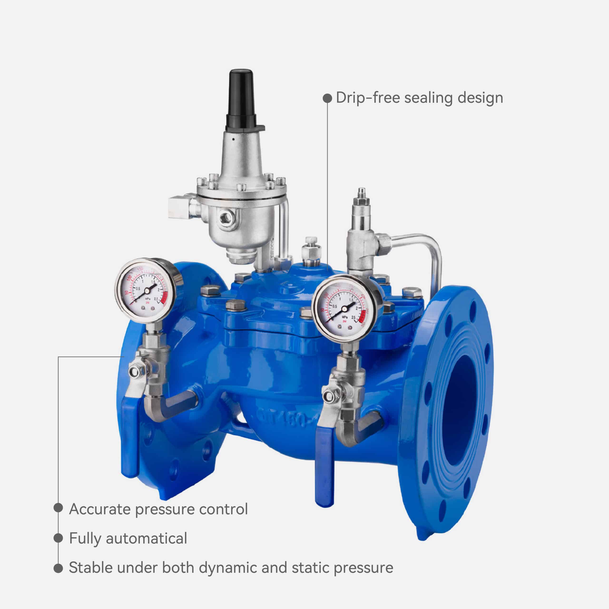
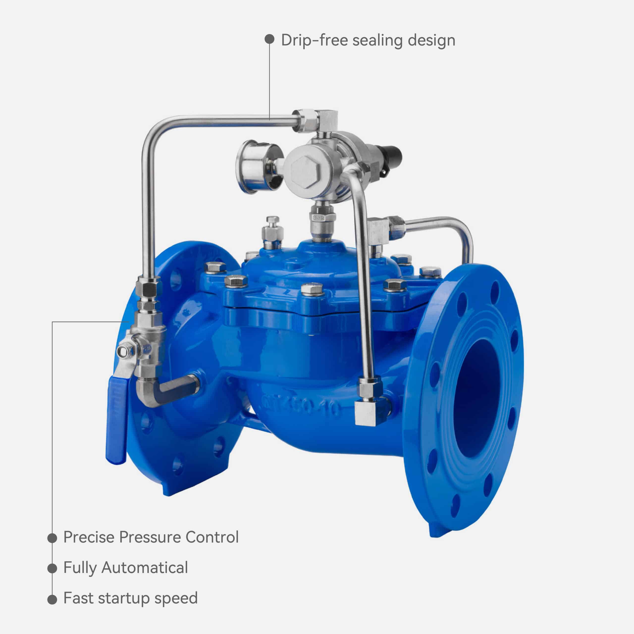
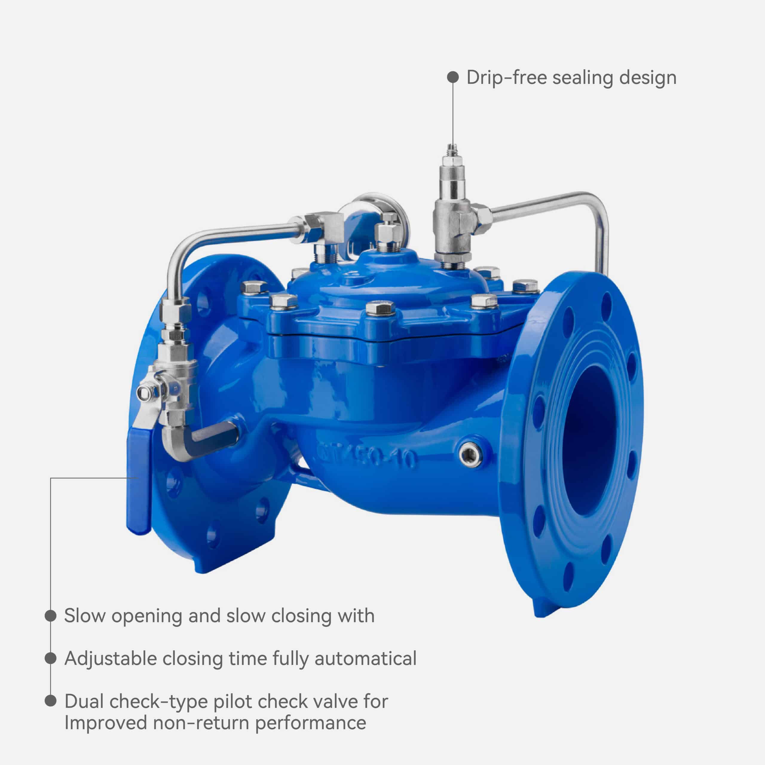
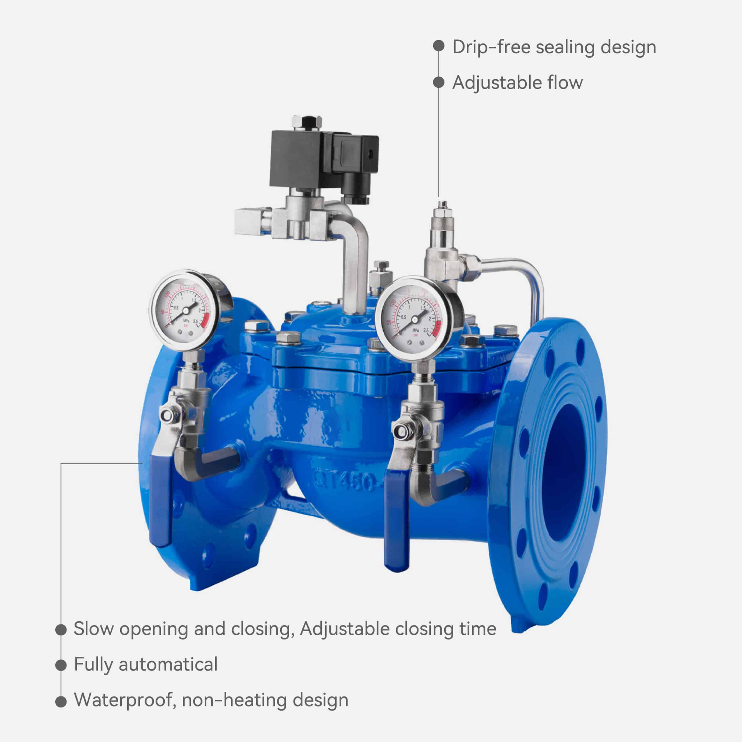
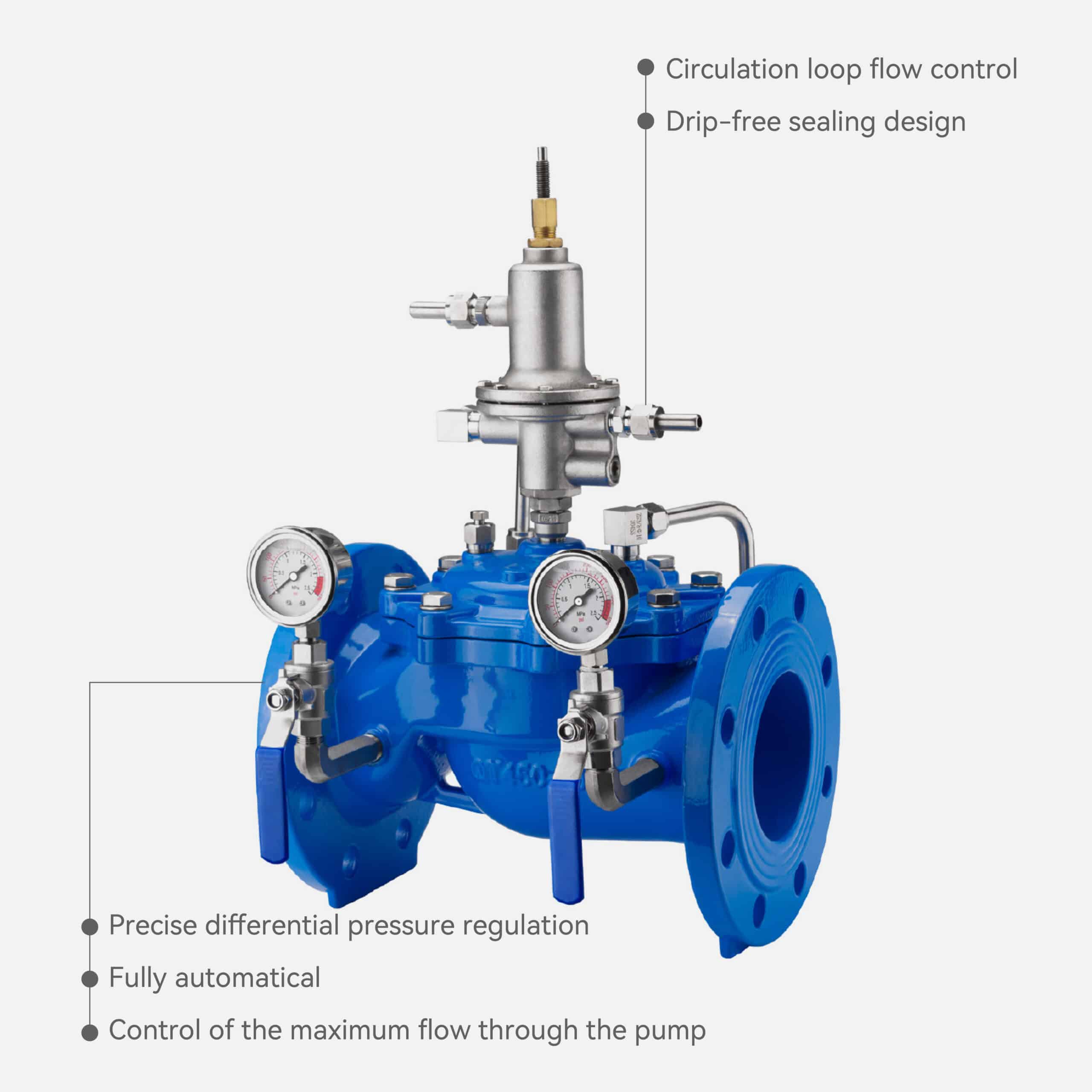
Feature
Technical Parameters
● Nominal Diameter: DN40–DN800
● Sealing Material: EPDM or NBR
● Operating Temperature: ≤ 80°C
● Applicable Medium: Clean water
● Valve Body Material: Ductile iron, brass, 304/316 stainless steel
● Flow Deviation:
PN10: ±8%
PN16: ±10%
PN25: ±12%
● Independent Pressure- Reducing Orifice Plate
● Drip-free sealing Design
● Precise Flow Limitation
● Fully Automatical
● Easy Adjustment

Working Principle
Judberd flow control valve is a hydraulically operated, pilot-controlled diaphragm valve designed to maintain a constant, pre-set maximum flow rate regardless of upstream pressure variations. Its operation is based on monitoring and regulating the differential pressure across an orifice plate installed downstream of the valve.
Differential Pressure Generated by the Orifice Plate
When water passes through the downstream orifice plate, a differential pressure (ΔP) is created between the upstream and downstream sides of the orifice:
Higher flow → Higher differential pressure
Lower flow → Lower differential pressure
This ΔP serves as the flow-proportional signal for the control system.
Pilot Valve Continuously Senses the Differential Pressure
The pilot control valve is connected to both sides of the orifice plate and continuously monitors the differential pressure.
The maximum allowable flow is set by adjusting the pilot valve’s adjustment screw, which corresponds to a specific ΔP value.
Excess Flow Causes the Main Valve to Modulate Toward the Closed Position
If the flow rate increases above the set value:
The differential pressure across the orifice rises
The pilot valve responds by reducing the pressure in the main valve’s control chamber
This causes the main valve to move toward a more closed position
As a result, the flow rate is automatically reduced back to the preset limit.
Insufficient Flow Causes the Main Valve to Open Further
If the system flow decreases:
The differential pressure drops
The pilot valve increases the control chamber pressure
The main valve opens further to allow more flow
This ensures the system receives the required flow rate while never exceeding the maximum setting.
Stable, Automatic Flow Regulation
Through continuous modulation of the main valve position, the system maintains:
Accurate flow limitation
Automatic compensation for pressure changes
Stable, repeatable flow control without external power
Judberd flow control valve uses the downstream orifice differential pressure as a feedback signal.
The pilot valve interprets this signal and hydraulically adjusts the main diaphragm valve opening,
ensuring the flow rate remains constant at the pre-set maximum value despite pressure fluctuations in the pipeline.
USE
Flow control valve is necessary in systems where you need to maintain a stable or limited maximum flow rate, regardless of pressure fluctuations.
Here are the most common and important applications and why you need a flow control valve.
Municipal Water Distribution
_
Upstream pressure varies significantly with peak and off-peak demand; A sudden pressure increase can cause excessive flow in distribution lines;Over-flow conditions lead to leakage, pipe stress, and potential burst events
● Flow control valve Can
Limits maximum flow to each zone, Stabilizes flow in branch lines and Protects pipelines from high-pressure flow surges
High-Rise Building Water Distribution
_
Pump discharge pressure is high and unstable; Lower floors receive excessive flow while upper floors may be under-supplied; Prevents flow imbalance throughout the building
● Flow control valve Can
Ensures fair and stable flow across different floors; Prevents excessive flow at lower levels and Improves overall supply reliability and system stability.
Pump Protection and Flow Limiting
_
Pumps operate best within a specific flow range; Too much flow → overload, vibration, cavitation risk or
Too little flow → overheating, unstable pump operation
● Flow control valve Can
Maintains pump flow within a safe operating zone; Prevents over-flow and protects pump performance and Reduces energy consumption and equipment wear
Agricultural Irrigation Systems
_
Irrigation network pressure often fluctuates; Each branch requires a stable and controlled flow and Excessive flow causes uneven irrigation and system imbalance
● Flow control valve Can
Provides accurate and uniform irrigation flow, Protects drip and sprinkler systems from over-flow and Maintains consistent irrigation performance
Industrial Cooling Systems
_
Industrial equipment requires a constant cooling water flow; Flow variation may affect cooling efficiency and Excessive flow increases energy consumption and can damage equipment
● Flow control valve Can
Ensures stable cooling water supply; Protects sensitive equipment from flow surges and Maintains efficient and reliable thermal control
Tank / Reservoir Filling Lines
_
Excessive filling flow causes overflow or unstable water level; Systems require controlled and gentle filling
● Flow control valve Can
Limits the maximum filling flow, Prevents overflow and protects level-control devices and Works perfectly together with float valves or level-control valves
DMA (District Metered Area) Network Flow Management
_
Water utilities must control maximum flow into each district; High flow during pressure peaks complicates leak detection and pressure zoning
● Flow control valve Can
Prevents over-flow into DMA zones, Maintains stable flow for leakage analysis and Improves overall pressure and distribution management
General Pipeline Protection
_
Downstream equipment has limited pressure/flow tolerance; Sudden flow surges cause water hammer, vibration, and stress ; Pumps, valves, meters, and filters need flow protection
● Flow control valve Can
Controls and limits flow surges, Protects downstream components from excessive hydraulic forces and Enhances system reliability and lifespan
You need a flow control valve when your system has below situation
Significant upstream pressure fluctuations
A risk of excessive flow
Equipment that must not exceed a maximum flow rate,
Multiple branches requiring balanced distribution
Pumps that must operate within a safe flow range
Sensitive downstream devices needing protection
The need to maintain stable system performance
Selection Guide
Selecting the right flow control valve is easy as long as you follow a few simple steps.Here is a clear, practical guide designed for people with no technical background.Just answer the questions in each step, and you will always get the right valve.
STEP 1 — Confirm the Pipe Size (DN)
Question:What is your pipeline diameter? DN50? DN150? DN300? Up to DN800?
Recommendation:Choose the same DN size as the pipeline.
If the valve is selected too small:
Noise increases
Pressure loss becomes high
Vibration may occur
Flow control accuracy decreases
Matching DN = safest and most stable choice.
STEP 2 — Define the Maximum Flow Rate You Want to Allow
This is the most critical parameter.
Ask yourself:What is the maximum flow I want to allow in this pipeline?”
Example: 150 m³/h, 250 m³/h, 500 m³/h, etc.
The flow control valve will automatically limit the flow to this value.
Important:Different maximum flows require different orifice plate sizes.
You do not need to calculate it yourself.
Just tell us the flow and we will design the correct orifice plate.
STEP 3 — Choose the Pressure Rating (PN10 / PN16 / PN25)
Question:What is the highest pressure in your system?
PN10 → for low and medium pressure systems
PN16 → for most municipal, commercial, and building systems
PN25 → for pumping stations, high-pressure networks, and industrial lines
Pressure rating must be equal to or higher than your working pressure.
STEP 4 — Select Connection Type
For DN50–DN800 sizes:
Flanged connection is standard and recommended
Strong, safe, and easy to install
Works for almost all water supply systems
Threaded connections are only for very small DN sizes or special cases.
STEP 5 — Choose Valve Body Material
Option 1: Ductile Iron (Standard), it is best for drinking water and general water supply, strong, reliable, cost-effective and recommended for 95% of applications
Option 2: Stainless Steel 304 / 316 , it is used for corrosive environments, for seawater or chemical conditions or for industrial fluids if compatible
If you use clean water → choose ductile iron unless there is corrosion concern.
STEP 6 — Choose Diaphragm / Seal Material (EPDM or NBR)
EPDM (Recommended for clean water) , it is safe for drinking water, excellent for normal water supply and good temperature resistance
NBR is used for water that contains oil or light hydrocarbons or special industrial fluids
STEP 7 — You always need an Orifice Plate ,flow control valve must work together with an orifice plate.The orifice plate creates a pressure difference (ΔP) that allows the valve to control flow.
And pleases pay attention the orifice plate size is not universal, different flow settings require different orifice diameters, and wrong orifice size will cause:
Loud noise, Excessive pressure loss, cavitation and poor flow control accuracy
You only need to tell us the flow.We will calculate the correct orifice plate size for you.
NBR is used for water that contains oil or light hydrocarbons or special industrial fluids
STEP 8 — To ensure you get the right valve, you only need to provide:Pipeline size (DN), Maximum flow you want (m³/h or L/s), Working pressure and PN rating, Medium (clean water? any oil?), Installation environment (normal / corrosive / coastal)
With this information, we will confirm:Correct DN, Correct pressure class, Correct body material, Correct seal material, Correct orifice plate size, Correct flow setting,
Everything will match your system.
Simple Example (Typical Customer Case)
Customer conditions:Pipeline: DN200; Maximum pressure: 12 bar; Medium: clean water; Required maximum flow: 200 m³/h;
Recommended configuration:DN200 Flow Control Valve; PN16; Ductile Iron Body;
EPDM diaphragm; Flanged ends; Orifice plate sized for 200 m³/h
The valve will automatically maintain 200 m³/h no matter how the pressure changes.
You don’t need to calculate anything.
Tell us your DN, pressure, maximum flow, and medium, and we will select the correct flow control valve and orifice plate for you.
Our goal is to make sure the valve works perfectly in your system without noise, pressure loss problems, or inaccurate flow control.
Adjustment
The Judberd Flow Control Valve is designed for simple and accurate flow adjustment.It does not require electricity, special tools, or advanced training.Follow the steps below to set the maximum flow safely and correctly.
1, Pre-Check Before Commissioning
Before starting the adjustment process, confirm the following
Installation direction
_
Ensure the valve is installed according to the flow arrow cast on the valve body.Incorrect flow direction will prevent proper operation.
Orifice plate installed downstream
_
The differential pressure across the orifice is essential for accurate flow control.Make sure the orifice plate is installed at the correct location and orientation.
System flushed clean
_
Debris may affect pilot valve sensitivity and diaphragm movement.
Upstream isolation valve and downstream isolation valve installed
_
Needed for safe commissioning and future maintenance.
2, Location of the Adjustment Screw
The maximum flow setting is adjusted on the pilot control valve, not on the main valve body.
The adjustment screw is on the top section of the pilot valve, Marked as “Adjustment” or shown in your Judberd drawing
Easily accessible after installation Requires only a flat-head screwdriver or small wrench (depending on model)
3, How to Set the Maximum Flow
Step 1
Open the upstream isolation valve slowly
_
This will allow water to fill the main valve and the pilot system gradually.
Step 2
Open downstream side
_
Ensure flow begins through the orifice plate.
Step 3
Adjust the pilot valve screw
_
● The direction is simple:
Turn clockwise → Decrease maximum flow(Pilot allows less differential pressure → main valve closes more), Turn counter-clockwise → Increase maximum flow (Pilot allows more differential pressure → main valve opens more)
● Notes:
Adjust slowly, ¼ turn at a time
Wait a few seconds after each adjustment for the valve to stabilize
Monitor flow meter reading (recommended) to fine-tune the setting
Judberd valves respond quickly and smoothly because of the sensitive pilot design.
Step 4
Confirm the flow is stable
_
When the system pressure changes (e.g., pump on/off), the valve should:
Automatically modulate
Keep the flow at or below the preset maximum
Maintain stable operation without vibration
If flow exceeds the setting, fine-tune again.
4, NO Need Professional Technician

Judberd flow control valves are designed for simple, tool-free, intuitive adjustment.

Anyone can set it if they can:Read a flow meter, Turn a screw, Follow the installation direction

No electrical connection, software, or calibration device is required.
5, Installation Requirements
To ensure correct function:
Choose a Pressure Relief & Sustaining Valve when you want to
maintain upstream pressure or prevent overpressure.
_
1, Ideal for pump discharge lines or main supply pipes.
2, Ensures stable inlet pressure and system protection.
Choose an Adjustable Pressure Reducing Valve when you want to
stabilize downstream pressure for users or equipment.
_
1, Ideal for zone distribution or building branches.
2, Ensures consistent outlet pressure regardless of upstream fluctuation.
Summary Table
| Parameter | Pressure Relief & Sustaining Valve | Adjustable Pressure Reducing Valve |
|---|---|---|
| Control Target | Upstream pressure | Downstream pressure |
| Main Function | Pressure relief & sustaining | Pressure reduction |
| Installation Position | Pump outlet / main pipeline | Distribution zone or end-user branch |
| Prevents Overpressure | Yes | No |
| Stabilizes Downstream Pressure | No | Yes |
| Dual Function Capability | Yes | Single function |
Pressure Relief & Sustaining Valve protects and stabilizes the supply side (upstream).
Pressure Reducing Valve protects and stabilizes the distribution side (downstream).
They look similar in structure but serve opposite control directions.
In large water networks, both valves are often used together — one at the pump outlet (sustaining) and one at the zone inlet (reducing) — to achieve complete system pressure management.
6, Key Advantages of Judberd Flow Control Valve During Adjustment
Easy flow setting
_
Flow limit is adjusted using only the pilot valve screw.
High accuracy
_
Pilot control ensures much higher precision than ordinary mechanical throttling valves.
No electricity needed
_
The valve operates purely by hydraulic power from the pipeline.
No special tools required
_
A screwdriver or small wrench is enough.
Fast response
_
Pilot valve reacts instantly to differential pressure changes.
Maintenance friendly
_
All adjustments can be done without removing the valve from the pipeline.
7, Recommended Simple Field Procedure (Quick Version)
01
Confirm flow direction and orifice installation
02
Open upstream valve → fill system
03
Open downstream valve
04
Turn pilot screw slowly
05
Watch flow meter to reach desired value
06
Lock the screw
07
Test system under pressure changes
08
Finalize setting and record value
Installation Guide

1, Important Notes Before You Start
This guide is for water service (clean or slightly dirty water).
The valve is directional
_
Water must flow in the same direction as the arrow on the body.
The valve works together with a downstream orifice plate
_
Do not omit it.
For safety
_
Always depressurize the pipeline and make sure no water can suddenly flow before installation.
2, Components You Should Have
Before installation, check that you have:
Judberd Flow Control Valve (main valve)
Pilot control valve and tubing (usually pre-assembled on the main valve)
Orifice plate (and its holder or matching flange, if supplied)
Gaskets for all flanged joints
Bolts, nuts, washers for flanges
If anything is missing or damaged, do not install – contact your supplier.
3, Piping Layout – Where Each Part Goes
From upstream to downstream, the recommended layout is:
Upstream pipe → Shut-off valve → Strainer (filter) → Straight pipe section → Judberd Flow Control Valve → Orifice plate → Downstream pipe / system
Strainer (filter) is Required upstream of the flow control valve ,it Protects the valve and pilot from debris.
Orifice plate Must be installed downstream of the main valve.
Typically installed between the first flange directly after the valve.
The orifice connects to the pilot control via small sensing tubes.
※ Straight pipe runs (recommended)
Upstream of the valve
_
Ideally keep a straight pipe length of at least 5 × DN (5 times the pipe diameter) after elbows, tees, or pumps, before the valve.
This helps achieve stable flow and reduces noise.
Downstream of the orifice plate
_
If possible, keep at least 3 × DN of straight pipe after the orifice for more stable differential pressure.
If the site conditions are limited and cannot meet these lengths, install as straight as possible and avoid immediately placing the valve/orifice right after sharp bends.
4, Step-by-Step Installation Procedure
STEP 1 – Make Sure the Pipeline Is Safe
Close all upstream and downstream shut-off valves.
Release pressure from the pipeline.
Make sure there is no water flow before you start work.
STEP 2 – Flush the Pipeline
Open the line briefly (without the valve installed) to flush out sand, rust, welding slag, and dirt.
Close the line again.
Skipping this step is one of the most common reasons for valve malfunction.
STEP 3 – Install the Upstream Strainer and Shut-Off Valve
Install a shut-off valve upstream (before the strainer).
Install a strainer after the upstream shut-off valve.
Make sure the strainer’s flow arrow matches the pipe flow direction.
Ensure there is enough space to open the strainer cover for cleaning in the future.
STEP 4 – Check Flow Direction on the Flow Control Valve
Find the arrow cast on the valve body.
Make sure the arrow matches the actual flow direction in the pipeline.
Common mistake: installing the valve backwards.
If the arrow is opposite to the water flow, the valve will not work correctly.
STEP 5 – Position and Support the Valve
Install the valve in a position that is: Easy to access the pilot and adjustment screw, Easy to see the nameplate and arrow
Make sure the valve is properly supported – do not let the full pipe weight hang on the valve alone.
Horizontal installation is usually preferred.
Vertical installation (flow from bottom to top) is also acceptable if allowed by your design.
STEP 6 – Install the Valve Between the Flanges
Place gaskets between the flanges on each side of the valve.
Align the valve so the bolt holes match.
Insert bolts and nuts.
Tighten bolts in a cross pattern (diagonally), little by little, to ensure even gasket compression.
Do not force the valve to “pull” misaligned pipes together – this can stress the body and cause leaks.
STEP 7 – Install the Orifice Plate Downstream
Locate the flange immediately downstream of the valve (or as specified in your drawing).
Place the orifice plate centered between the flanges with gaskets.
If the orifice plate has a mark indicating upstream side, ensure this side faces the valve.
Tighten flange bolts evenly in a cross pattern.
Make sure any sensing connections from the orifice to the pilot valve are correctly connected and not twisted or kinked.
Important:
Orifice plate size is matched to the required flow.
Do not replace or modify it yourself – wrong size causes noise, high pressure loss, and poor control.
STEP 8 – Check Pilot Tubing and Accessories
Ensure all pilot tubes are connected firmly to their ports (no loose fittings).
Make sure tubes are not bent sharply, twisted, or squeezed.
Check that any small valves on the pilot lines (if present) are fully open unless the manual says otherwise.
STEP 9 – Initial Filling and Leak Check
Slowly open the upstream shut-off valve to allow water to fill the valve and pilot system.
Check all flanged joints, pilot connections, and orifice flanges for leaks.
If any leaks are found, close the valve, release pressure, and re-tighten or re-gasket as necessary.
STEP 10 – Open Downstream Line and Prepare for Adjustment
Slowly open the downstream shut-off valve.
Let water flow through the valve, orifice plate, and downstream system.
The valve will begin to work, but the flow limit may not yet be adjusted – this will be done in the commissioning / setting step (you already have that guide).
5, Installation Checklist (For Non-Experienced Users)
Before you say “installation completed”, quickly check:
Valve arrow points in the correct flow direction
Strainer installed upstream of the valve
Orifice plate installed downstream of the valve
All flanges have gaskets and are tightened in a cross pattern
Pilot tubes are connected, not twisted or damaged
Pipeline was flushed before installing the valve
Upstream and downstream shut-off valves are installed
If all boxes are ticked, your valve is installed correctly and ready for flow setting and commissioning.
6, Common Mistakes to Avoid
Through continuous modulation of the main valve position, the system maintains:
Installing the valve backwards (arrow opposite to flow)
_
● Forgetting the downstream orifice plate or installing it incorrectly
● No strainer upstream – dirt damages the valve and pilot
Not flushing the pipeline before installation
_
● Over-tightening or unevenly tightening bolts causing gasket damage
● Using the valve to “pull” misaligned piping into place
● Bending or crushing the pilot tubes
FAQ
1, Flow hunts (flow goes up and down repeatedly)
Possible Causes
● Upstream pressure is unstable, The valve is designed to modulate based on differential pressure. Large pressure fluctuations cause frequent adjustments.
● Orifice plate installed incorrectly or wrong size, Incorrect orifice size causes unstable differential pressure (ΔP), leading to unstable flow.
● Pilot needle valves not fully open, If the pilot needle valves are partially closed, the control response becomes delayed and unstable.
● Air trapped in the pilot system , Air pockets reduce sensitivity, causing hunting (repeated opening/closing).
Solutions
● Check upstream pressure and try to stabilize it.
● Verify the orifice plate is correct, properly sized, and installed downstream.
● Make sure all pilot isolation valves are fully open.
● Bleed air from the pilot lines and main valve cover.
● Confirm the flow setting is correct (adjust pilot screw gradually).
2, System pressure changes cause unstable flow or unstable water supply
Possible Causes
● Missing orifice plate
● The valve cannot regulate without the ΔP generated by the orifice plate.
● Blockage in orifice drilling or pilot tubing
● Dirt or debris reduces the ΔP signal accuracy.
● Upstream filter (strainer) clogged
● Reduces upstream pressure → valve opens incorrectly.
Solutions
● Ensure the orifice plate is installed, and that the sensing lines are properly connected.
● Remove blockages from pilot tubes or orifice.
● Clean the upstream strainer.
● Verify the valve installation direction is correct (arrow must match flow).
3, Valve hums or vibrates
Possible Causes
● Orifice plate too small
● Excessive pressure loss and high velocity cause noise and vibration.
● Flow velocity too high
● The flow is exceeding recommended limits for the pipe size or the set flow.
● Cavitation inside the valve
● Happens when the pressure drop is too high.
● Valve installed immediately after an elbow, pump, or reducer
● Turbulent flow enters the valve directly.
Solutions
● Check if the orifice plate matches the required maximum flow.
● If undersized → replace with correct size.
● Reduce the flow setting (turn pilot clockwise).
● Ensure 5 × DN straight pipe length upstream if possible.
● Avoid installing the valve immediately after pumps/fittings.
● Check system pressure to ensure the valve is operating within safe ΔP range.
4, Flow cannot be adjusted or response is very slow
Possible Causes
● Pilot valve adjustment screw not functioning
● Often due to dirt or internal blockage.
● Pilot isolation valves closed
● The pilot cannot sense the orifice ΔP.
● Pilot tubing blocked or kinked
● No differential pressure signal reaches the pilot.
● Main valve diaphragm damaged
● Causes valve not to modulate.
● Using too small or incorrectly sized orifice plate
● ΔP too high → pilot loses control.
Solutions
● Clean or replace the pilot valve.
● Check all pilot valves (needle valves) are fully open.
● Inspect pilot lines for twisting, bending, or blockage.
● Check diaphragm integrity; replace if necessary.
● Verify correct orifice plate size based on required flow.
5, Flow always higher than the set value (cannot limit flow)
Possible Causes
● Orifice plate too large
● Differential pressure too low → pilot cannot sense flow.
● Pilot adjustment screw turned too far counterclockwise
● Opening too wide → higher flow allowed.
● Pilot valve stuck or faulty
● Cannot respond to ΔP.
● Bypass tubing leakage
● Pressure equalizes, making control inaccurate.
Solutions
● Replace with correctly sized orifice plate.
● Gradually turn clockwise to reduce maximum flow.
● Clean or replace pilot valve.
● Tighten or replace tubing fittings.
6, Flow much lower than expected
Possible Causes
● Orifice plate too small
● Excessive pressure loss.
● Strainer clogged
● Upstream pressure reduced.
● Pilot needle valve not fully open
● Restricts pilot flow.
● Main valve not fully open due to internal blockage
● Calcium, sand, or debris under the diaphragm.
Solutions
● Verify correct orifice size.
● Clean upstream strainer.
● Open all pilot valves fully.
● Clean main valve internals if blockage exists.
7, Flow response delayed or valve reacts slowly
Possible Causes
● Air in pilot lines or valve cover
● Compressible air reduces sensitivity.
● Pilot valve contaminated or partially blocked
● Slows pressure transmission.
● Pilot tubing too long or installed with sharp bends
● Slows hydraulic feedback.
● Main diaphragm aging or stiff
● Slow movement.
Solutions
● Bleed air from pilot system.
● Clean or replace pilot valve.
● Shorten or straighten pilot tubing.
● Replace diaphragm if aged.
8, Valve does not work at all
Possible Causes
● Flow direction reversed
● Installed opposite the flow arrow.
● Orifice plate missing
● No ΔP = no control.
● Pilot tubing completely blocked
● No signal to the pilot.
● Strainer completely clogged
● No upstream pressure.
Solutions
● Reinstall the valve in the correct direction.
● Install the correct orifice plate.
● Clean pilot tubes and fittings.
● Clean the strainer.
9, Noise, water hammer, or high vibration after installation
Possible Causes
● Valve installed right after a pump or elbow
● Orifice plate too small
● Flow rate set too high
● System running above designed pressure
Solutions
● Add straight pipe section upstream.
● Replace orifice plate with correct size.
● Reduce maximum flow setting.
● Check pressure and stabilize system.
10, General Preventive Measures (Avoid Problems Before They Happen)
● Install strainer upstream and clean it regularly.
● Always install the orifice plate downstream.
● Make sure the flow direction arrow is correct.
● Flush pipelines before installation.
● Keep pilot tubing straight and clean.
● Adjust the flow slowly, ¼ turn at a time.
● Ensure the system is free from air.