High-pressure pipeline failures are a nightmare. A pipe pull-out causes massive damage and safety risks. But you can prevent this with the right engineering and restraint systems.
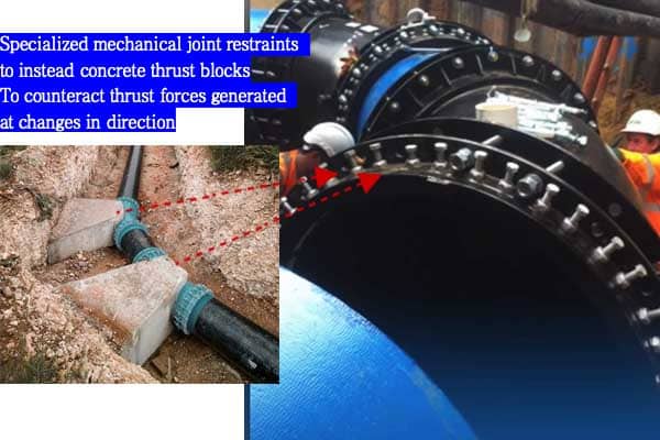
To prevent pipe pull-out, you must counteract thrust forces generated at changes in direction. This is done by identifying high-risk locations like bends and tees and installing appropriate support, such as concrete thrust blocks or specialized mechanical joint restraints designed for your specific pipe material.
I've seen firsthand the chaos a single failed joint can cause on a major project. It's not a pretty sight. The ground gives way, water erupts, and a critical service line is suddenly out of commission. But the good news is, these failures are almost always preventable. To really secure your pipeline, you first need to understand what you're up against. Let's start by looking at the root causes of this dangerous problem.
What Causes Pipe Pull-Out in High Pressure Pipelines?
Don't understand the forces in your pipeline? Ignoring them can lead to unexpected joint separation and failure. Knowing the cause is the first step to a secure system.
Pipe pull-out is caused by dynamic and static thrust forces. These forces are generated by the water pressure acting on the pipe at any point where the flow changes direction or stops, like at bends, tees, reducers, and dead ends. This force pushes the fittings apart.
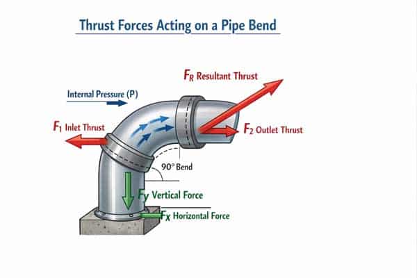
Let's dive deeper into these forces. Imagine you turn on a fire hose. The nozzle whips around with incredible force unless it's held firmly. Your pipeline experiences the same kind of force, just on a much larger and more constant scale. We call this "thrust force."
Understanding Thrust Forces
Thrust force is the invisible enemy in every pressurized pipeline. It is created by the internal water pressure pushing against the internal surfaces of fittings. Any time water changes direction or the pipe size changes, this force tries to push the pipe and fittings apart. There are two main types of forces to consider:
- Static Force : This is the constant force from the consistent water pressure inside the pipeline when the water is not moving.
- Dynamic Force: This is a sudden, additional force caused by changes in the water's velocity. We often call this "water hammer " or a "pressure surge." It happens when a valve is closed or opened too quickly.
The total thrust force can be massive, especially in large-diameter, high-pressure lines. The table below shows how quickly the force increases.
| Pipe Size (DN) | Pressure (Bar) | Approximate Thrust Force at 90° Bend (kg) |
|---|---|---|
| 300 | 10 | 10,000 |
| 600 | 10 | 40,000 |
| 1200 | 10 | 160,000 |
As you can see, these are not small forces. Without a proper restraint system, this force will push a joint apart, causing a pull-out.
Where Are the Highest Risk Locations for Pipe Pull-Out?
Think all parts of your pipeline are equally safe? Some locations are ticking time bombs for pull-out. Ignoring these high-risk zones is a recipe for disaster and expensive repairs.
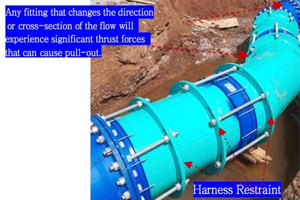
The highest risk locations are points of change in the pipeline. This includes horizontal and vertical bends, tees, wyes, reducers, and dead ends or plugs. Any fitting that changes the direction or cross-section of the flow will experience significant thrust forces that can cause pull-out.
In our 30 years of manufacturing pipe components, I've learned that you have to think like water. Where is the pressure going to push? Any change is a point of weakness if it's not properly supported. Let's break down the most common high-risk spots you need to protect.
Key Hotspots for Thrust Forces
Not all fittings are created equal when it comes to risk. The geometry of the fitting directly impacts the magnitude and direction of the thrust force.
| Fitting Type | Risk Level | Why It's a Risk |
|---|---|---|
| Dead Ends / Caps | High | The entire force of the water column pushes directly outward. |
| 90° Bends / Elbows | High | The force tries to push the bend outward at a 45° angle from the pipes. |
| Tees / Crosses | High | Multiple forces act on the main line and the branch line, pushing them apart. |
| 45° Bends / Elbows | Medium | The change in direction is less sharp, so the resulting thrust force is lower. |
| Reducers / Expanders | Medium | Force is generated by the pressure acting on the changing diameter area. |
- Bends and Elbows: These are the most common points of failure. A 90° bend experiences about 1.4 times the force of a dead end on the same line. The force acts to straighten the pipeline, pushing the bend away from the connecting pipes.
- Tees and Crosses: When flow is diverted into a branch, a force is created that tries to push the branch pipe away from the main line. If the main line is also capped just after the tee, the forces become very complex and large.
- Dead Ends: This is where the pipeline stops. It's like a piston, with the full force of the water pressure pushing directly on the cap or plug. It's a simple but very powerful force.
Understanding these locations is critical. Every single one of them needs a plan for restraint.
Engineering Methods to Prevent Pipe Pull-Out (Thrust Blocks vs Restraints)?
Choosing between thrust blocks and restraints can be confusing. The wrong choice could fail under pressure, compromising your entire pipeline. Let's clarify which method is right for your project.
Thrust blocks use large concrete masses to resist force by transferring it to the surrounding soil. Mechanical joint restraints, however, create a continuous, restrained pipeline that distributes the force along the pipe itself. Restraints are often faster, more reliable, and suitable where soil conditions are poor.
For decades, concrete thrust blocks were the standard. I remember projects where we'd wait for days for the concrete to cure before we could even think about pressure testing. But times have changed. Modern mechanical restraints offer a completely different approach, and in many cases, a much better one. Let's compare the two methods.
The Traditional Method: Concrete Thrust Blocks
A thrust block is essentially a giant, specifically shaped block of concrete poured behind a fitting. It works by taking the thrust force from the fitting and spreading it over a large area of undisturbed soil. The soil pushes back, holding the fitting in place.
- Pros: The material itself (concrete) is cheap.
- Cons: This method is full of problems. It requires a huge hole, which costs time and money to dig. You have to wait 7-28 days for the concrete to cure and reach full strength. And its effectiveness depends entirely on the soil's bearing capacity. If the soil is weak or wet, the block can move, and your pipe will pull out.
The Modern Solution: Mechanical Joint Restraints
Mechanical joint restraints are engineered devices that grip the pipe and connect it directly to the fitting. This makes the pipe and fitting act as one solid unit. Instead of pushing against the soil, the thrust force is transferred along the pipe itself, using the pipe's own tensile strength and the friction of the soil along its length.
- Pros: They are incredibly fast to install, often in under an hour. You can pressure test the line immediately. They work in any soil condition, are easy to inspect, and don't interfere with future digging nearby.
- Cons: The initial purchase price of the restraint is higher than the cost of a bag of concrete.
Here is a simple comparison:
| Feature | Concrete Thrust Blocks | Mechanical Joint Restraints |
|---|---|---|
| Installation Time | Days to weeks (with curing) | Minutes to hours |
| Reliability | Depends on soil quality | Engineered, consistent performance |
| Total Cost | High (labor, excavation, delays) | Lower (fast, less labor) |
| Inspection | Impossible after backfill | Easy to access and inspect |
| Future Work | Major obstacle | Does not interfere with excavations |
For our customers, who are focused on quality and project deadlines, the choice is clear. Mechanical restraints provide the reliability and speed that modern engineering projects demand.
How to Select the Right Restraint System for Different Pipe Materials?
Think one type of restraint fits all pipes? Using a restraint designed for steel on a plastic pipe can cause it to fail. You need to match the system to the material.
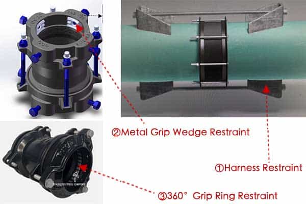
The right restraint depends on the pipe's strength and surface properties. Rigid pipes like ductile iron can handle aggressive grip-block designs. Softer pipes like HDPE require 360-degree clamping systems to distribute force evenly and prevent damage. For very large pipes, a harness system is often best.
As a manufacturer with our own R&D department, this is where we spend a lot of our time. We don't believe in a one-size-fits-all solution. A pipe is only as strong as its weakest link, and an mismatched restraint is a very weak link. We've designed specific solutions because different pipe materials behave differently under pressure.
For High-Strength Rigid Pipes (Ductile Iron, Steel)
Ductile iron and steel pipes are incredibly strong and rigid. They can handle a lot of localized stress without deforming. For these materials, we developed a grip-block restraint design . This system uses a series of hardened metal teeth set into a gland. The design is clever: as thrust force tries to pull the pipe out of the fitting, the gland is pulled tighter, and the teeth bite deeper into the pipe's surface. This creates an incredibly strong mechanical lock that gets stronger as the force increases. It's a brute-force solution for a brute-force material.
For Flexible Pipes (HDPE, PVC)
HDPE and PVC pipes are different. They are more flexible and can be damaged by the sharp teeth used on iron pipes. A major challenge with these materials is "creep," where the plastic slowly deforms over time under a constant load. A point load from a sharp tooth could eventually cause a leak or failure. To solve this, we designed a 360-degree gripping system . Instead of teeth, this restraint uses a series of gripping segments that encircle the pipe completely. When tightened, it applies uniform pressure around the entire circumference. This distributes the restraining force over a large surface area, providing a secure grip without creating stress points that could damage the pipe.
For Very Large Diameter Pipelines (>DN1500)
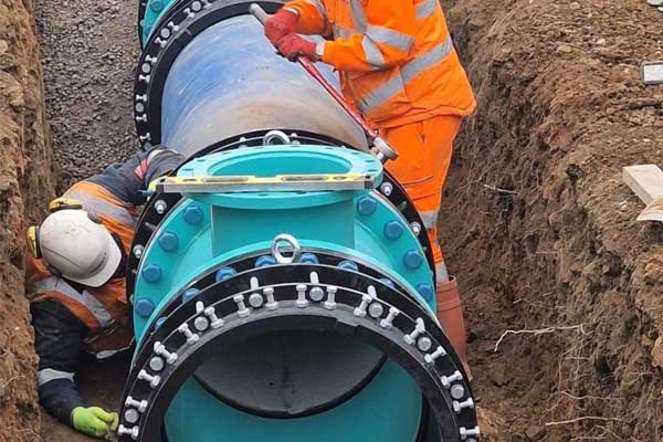
When you get to pipelines over 1.5 meters in diameter, the forces involved are astronomical. A standard restraint might not be enough. For these massive projects, we use a harness-type restraint system. This approach involves welding high-strength steel lugs directly onto the pipe sections on either side of the joint. Steel rods or plates are then used to connect the lugs on the fitting to the lugs on the pipe. It's a heavy-duty, fully engineered solution that ensures the entire assembly is locked together, capable of withstanding the immense thrust forces.
Installation Mistakes That Lead to Pipe Pull-Out (And How to Avoid Them)?
Your expensive restraint system is installed. But is it done right? Simple installation errors can render it useless, leading to the very failure you tried to prevent.
Common mistakes include improper bolt tightening (under or over-torquing), failing to clean the pipe surface, incorrect alignment of the restraint, and not following the manufacturer's instructions. Always use a torque wrench, ensure surfaces are clean and dry, and double-check alignment before backfilling.
A perfect product can fail if it's installed incorrectly. Over the years, we've seen it all. The frustrating part is that these mistakes are almost always avoidable. As a manufacturer, we provide detailed instructions for a reason: we want your project to succeed. Here are the most common errors we see in the field and how to prevent them.
Mistake 1: Incorrect Bolt Torquing
This is the number one problem. The bolts on a restraint need to be tightened to a specific torque value.
- Under-tightening: If the bolts are too loose, the restraint won't have enough clamping force to grip the pipe. Under a pressure surge, it will simply slip.
- Over-tightening: If the bolts are too tight, you can strip the threads, break the bolt, or even crack the restraint gland or the pipe fitting itself.
- How to Avoid: Always use a calibrated torque wrench. Never use a standard wrench and guess. Follow the torque specifications in the manufacturer's installation manual. Tighten bolts in a star pattern to ensure even pressure.
Mistake 2: Contaminated Pipe Surfaces
Mechanical restraints work by creating friction and biting into the pipe surface. This connection can be compromised by contaminants.
- The Problem: Grease, oil, mud, ice, or even excessive water can act as a lubricant. This will dramatically reduce the gripping power of the restraint.
- How to Avoid: Before you install the restraint, thoroughly clean and dry the section of pipe where the gland will sit. The surface should be free of all debris.
Mistake 3: Misalignment
A restraint is designed to apply force evenly. If it's installed at an angle, the forces become concentrated on one side.
- The Problem: An improperly seated or misaligned restraint will not perform to its specified rating. The uneven load can lead to a localized failure of the gland or an insufficient grip on the pipe.
- How to Avoid: Take a moment before final tightening to ensure the restraint gland is sitting straight and is properly aligned with the pipe and fitting. Make sure the pipe is fully inserted into the fittings's socket.
Conclusion
Preventing pipe pull-out boils down to understanding thrust forces, identifying risk areas, and choosing and correctly installing the right restraint system for your specific pipe material and project needs.
