| 1. Excessive Pressure Differential (ΔP too high) | The inlet pressure is much higher than the outlet pressure, leading to a sharp pressure drop inside the valve. | High-pressure transmission → low-pressure distribution |
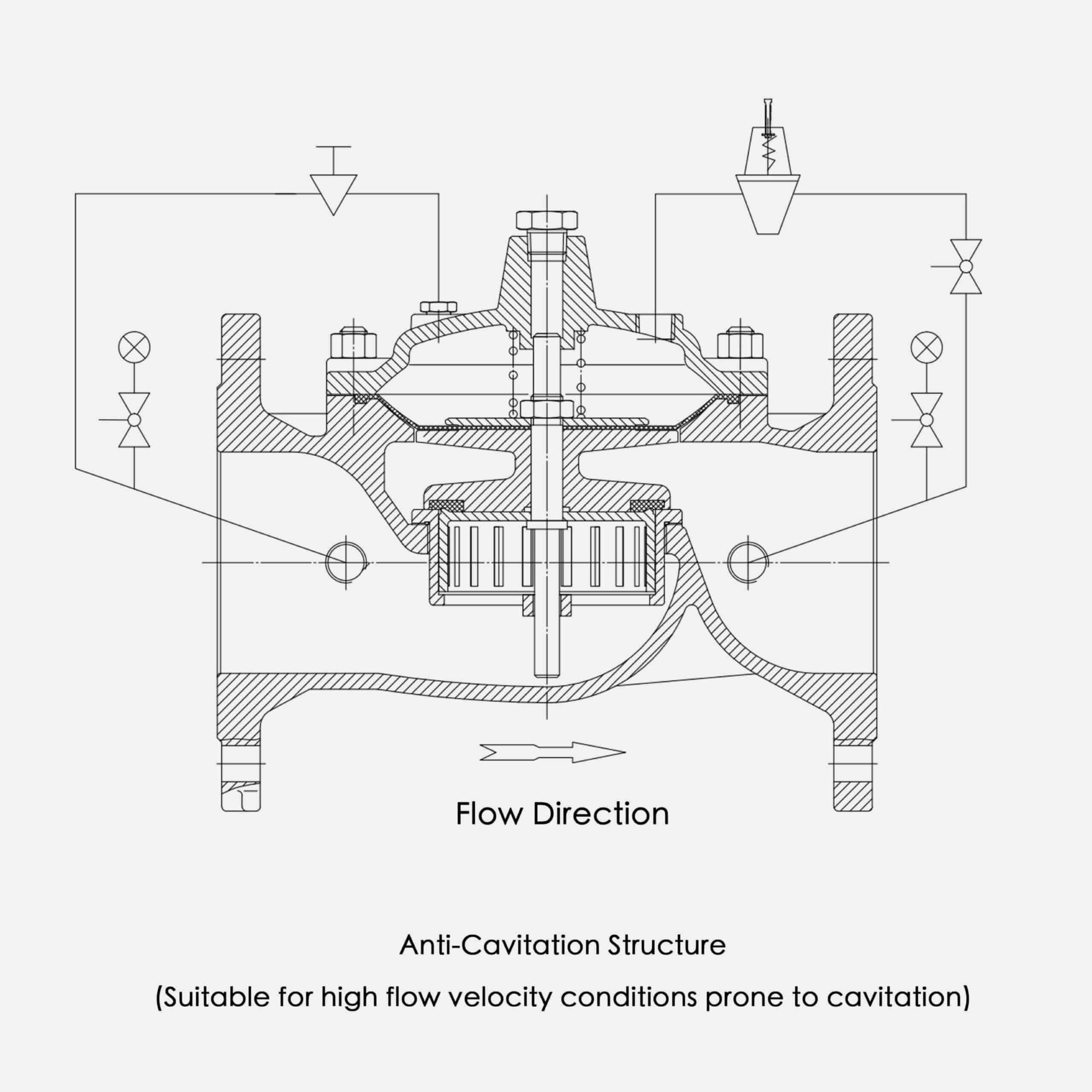
| 2. Excessive Flow Velocity | When the flow rate or valve opening is too large, the velocity near the seat or orifice increases sharply, causing a pressure drop below vapor pressure. | Operation at small openings or high flow conditions |
| 3. Outlet Pressure Set Too Low | If the set outlet pressure is too low, part of the valve interior may fall below the vapor pressure. | Users pursuing an excessive pressure reduction ratio |
| 4. High Fluid Temperature | Higher temperature reduces the vapor pressure of the fluid, making cavitation easier to occur. | Hot water or industrial circulation systems |
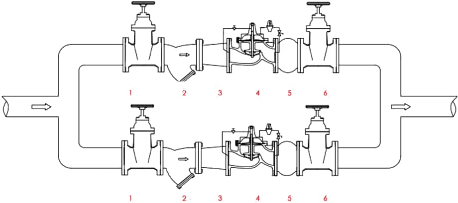
| 5. Poor Piping Design | Elbows, reducers, or short straight runs before/after the valve cause turbulence and local pressure fluctuations. | Valve installed near elbows or pump outlets |