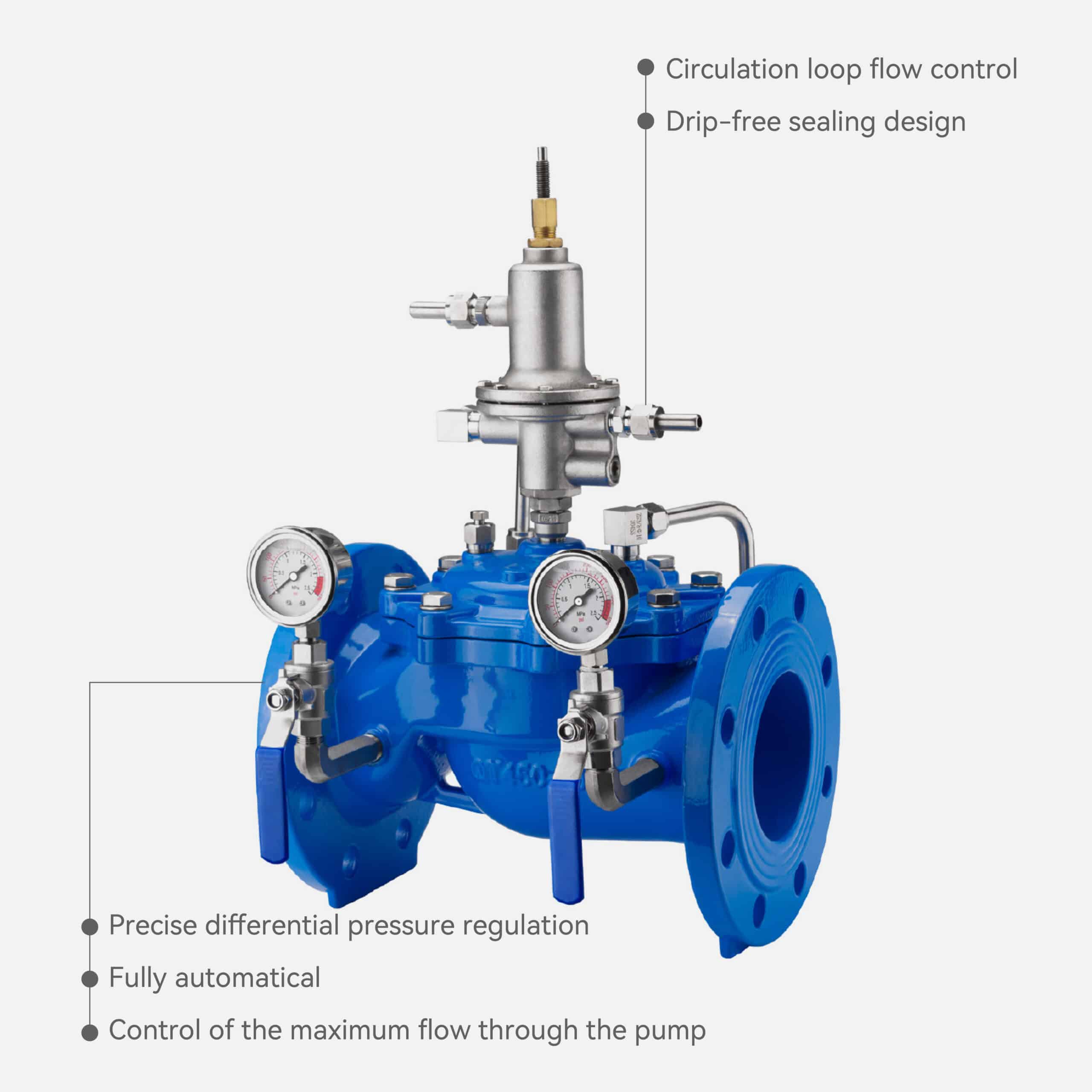
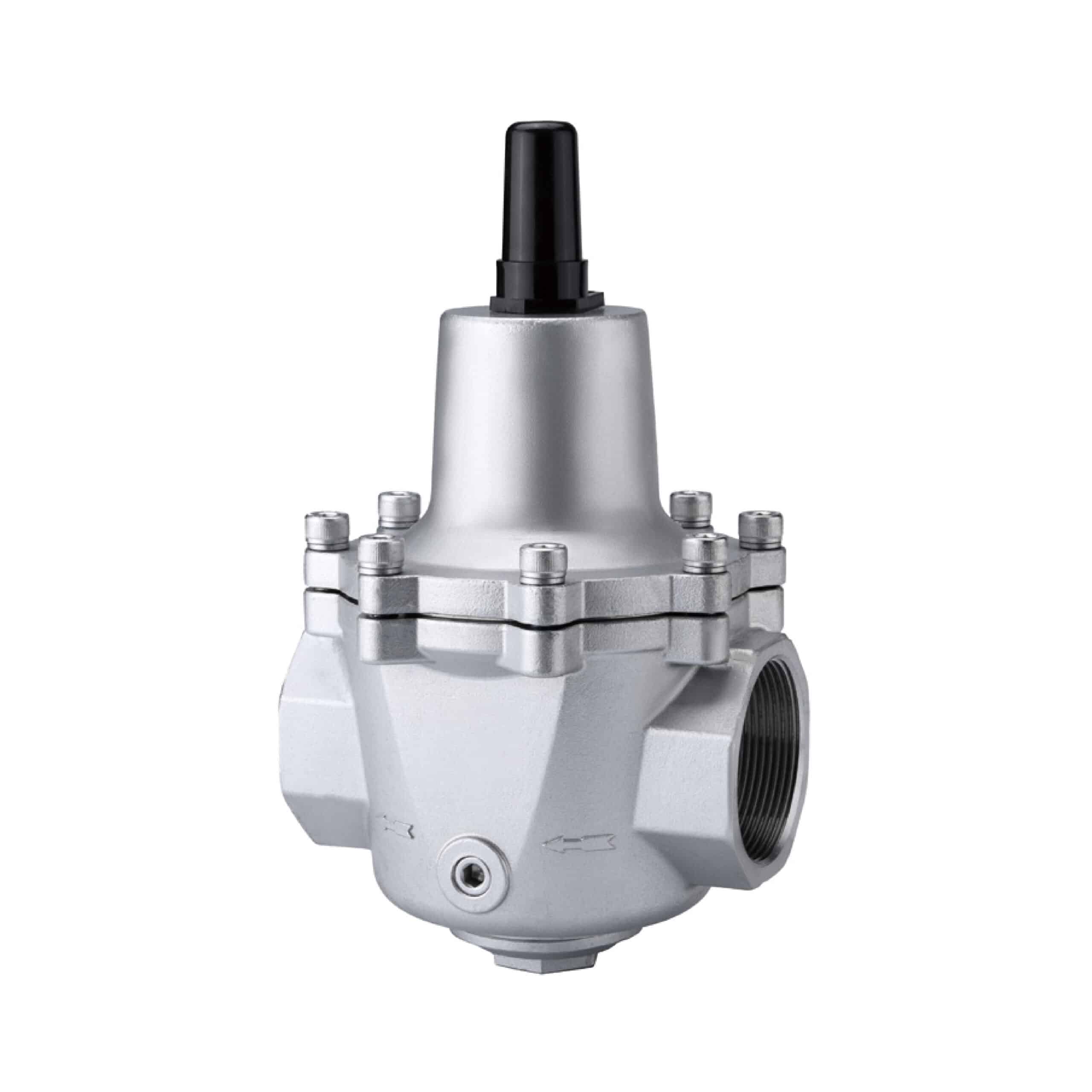
Full-flow Threaded Branch Pressure Reducing Valve
The Full-flow Threaded Branch Pressure Reducing Valve is a direct-acting type pressure reducing valve that automatically regulates outlet pressure through an internal spring and diaphragm (or piston) mechanism, without the need for an external pilot system.
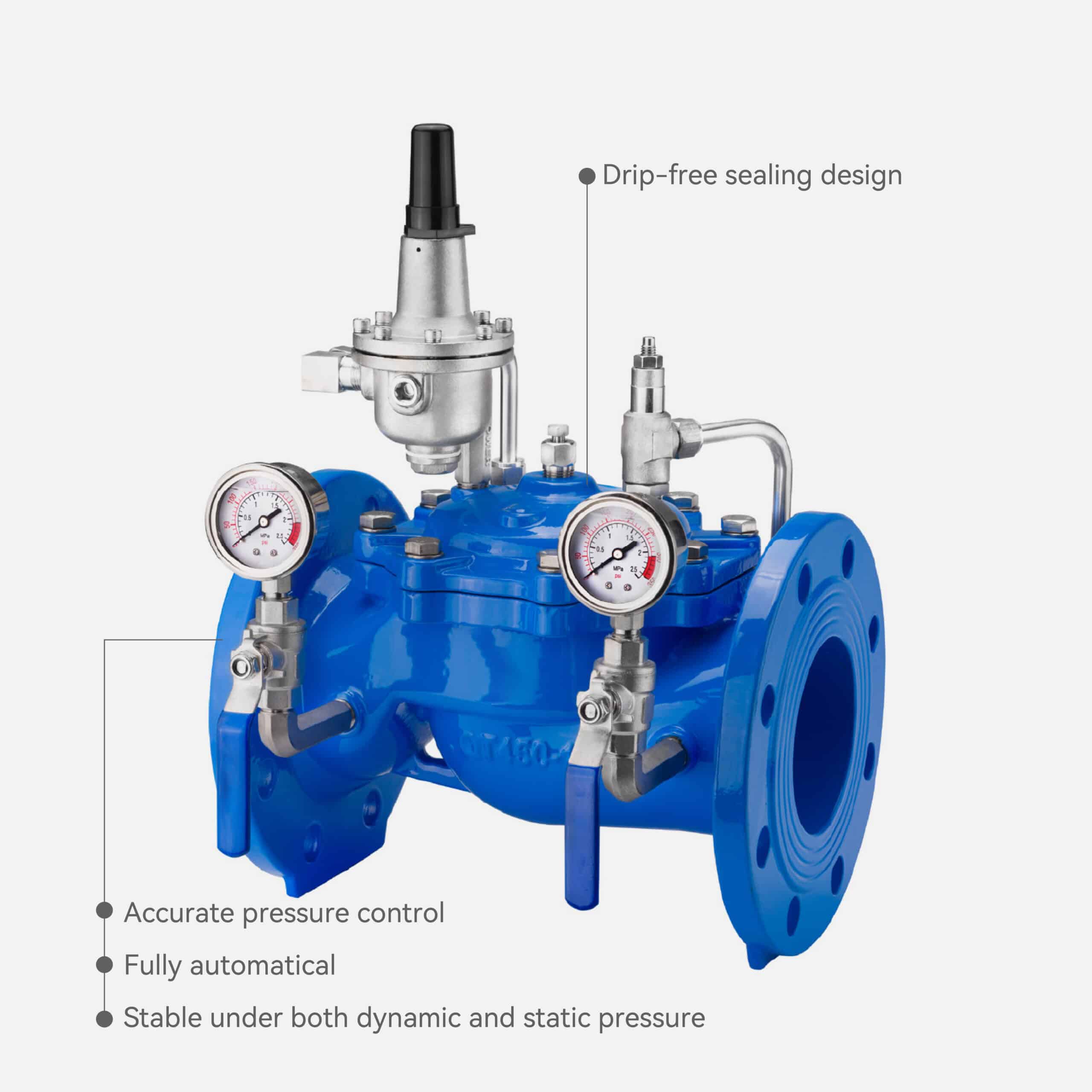
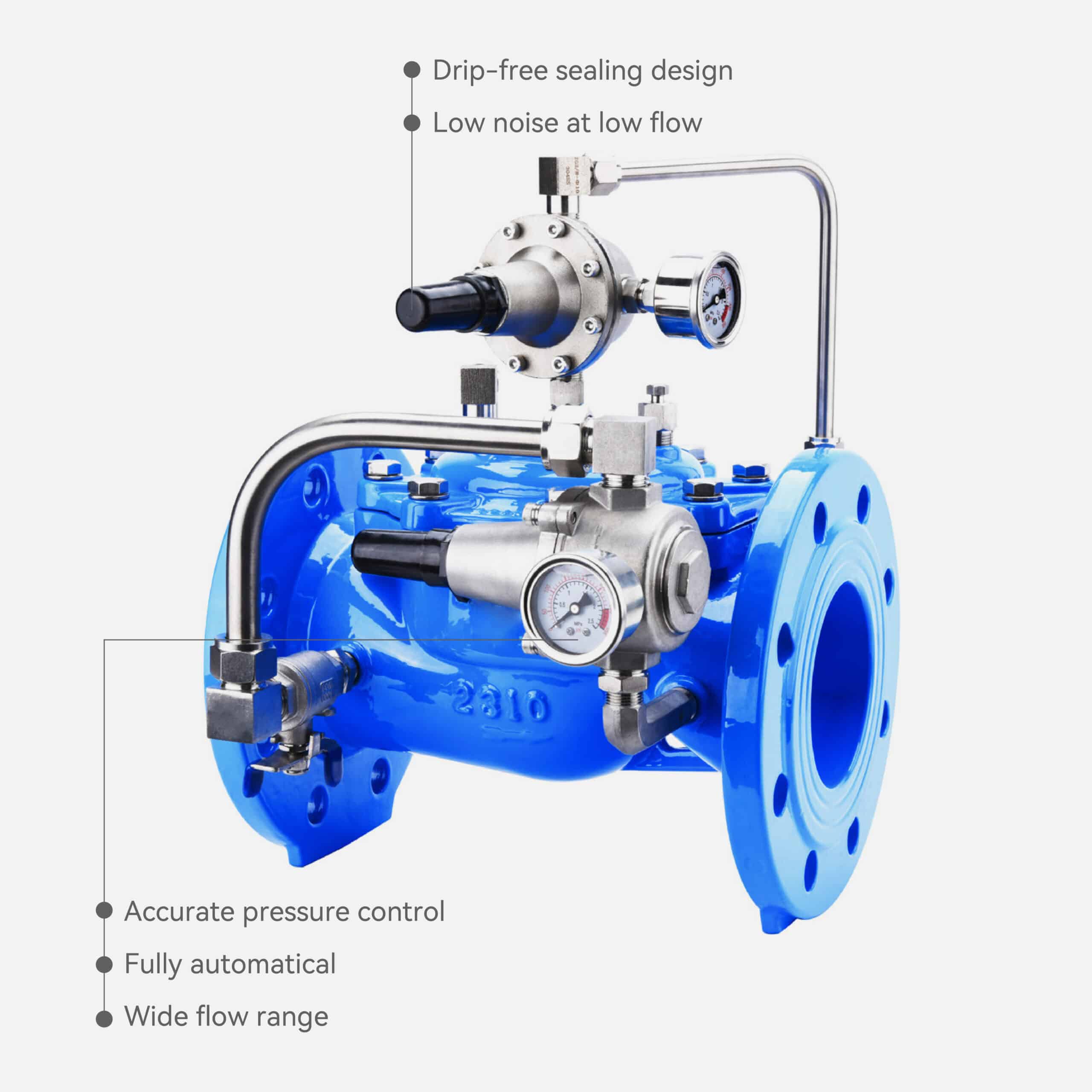
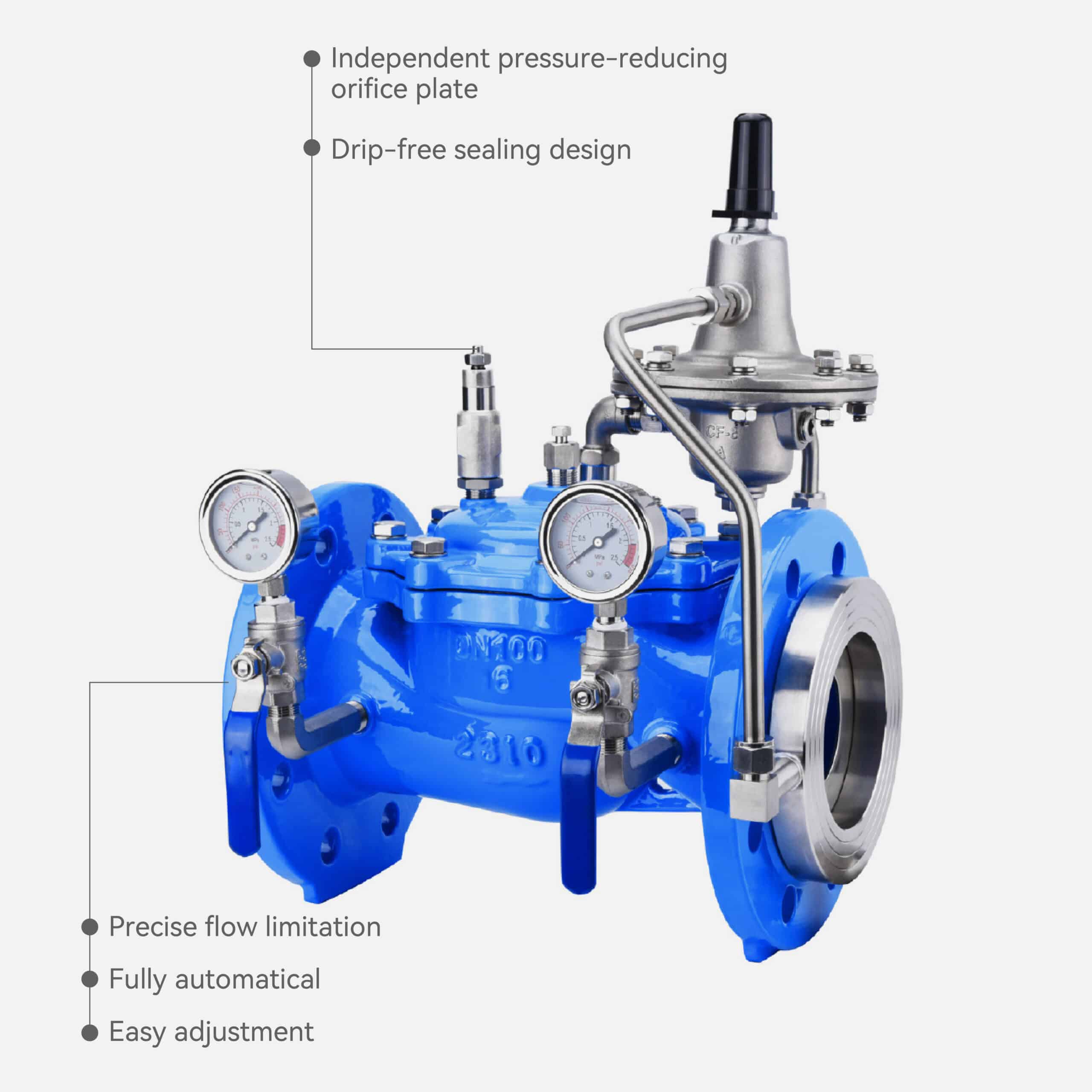
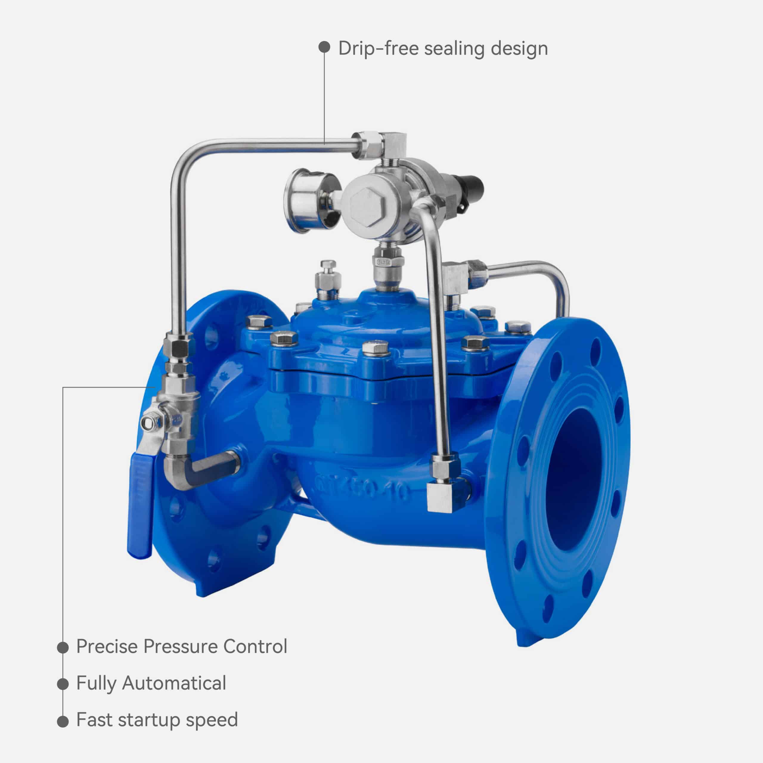
Featuring a full-bore design, it ensures precise and stable pressure control over a wide flow range with minimal pressure loss and large flow capacity.
Compact in structure and easy to install or maintain, it is widely used in building water supply, HVAC circulation systems, and industrial branch pipelines for local pressure regulation in small to medium flow applications.
Feature
● Direct-acting – precise pressure control
● Full-bore design – large flow capacity
● Wide operating flow range
● Easy installation and maintenance
● The PLBP threaded branch pressure reducing valve automatically converts high inlet pressure into the required stable and lower outlet pressure, maintaining constant static pressure over the long term.
● Nominal Diameter DN15 ~ DN50
● Inlet Pressure Range ≤1.6 MPa
● Outlet Pressure Range 0.1 MPa ~ 0.5 MPa
● Working Temperature 0°C ~ 85°C
● Applicable Medium Water
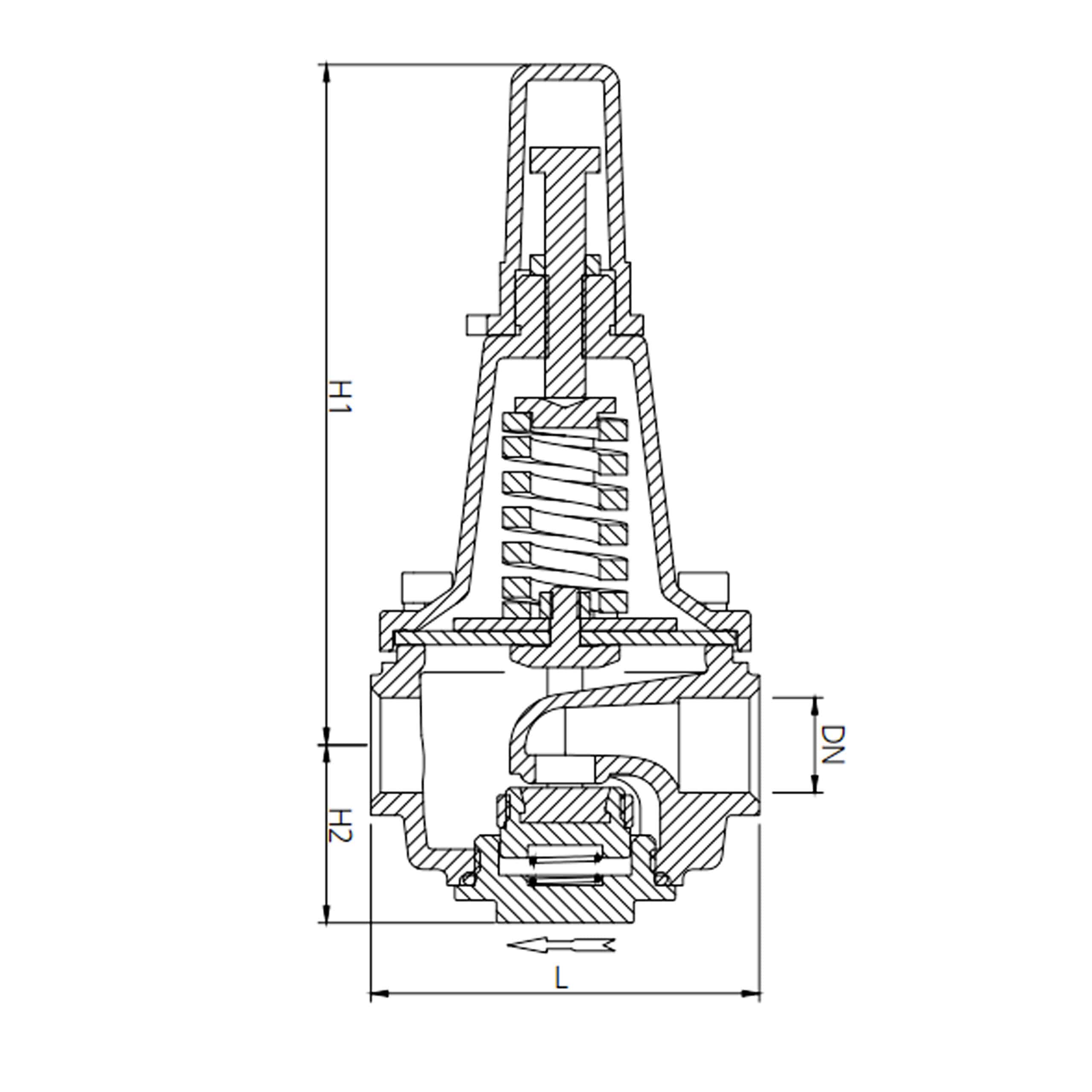
Drawing
Material
| Parts | Material |
|---|---|
| Valve Body | Stainless Steel |
| Valve Cover | Stainless Steel |
| Valve Core | Stainless Steel |
| Valve Disc | Stainless Steel |
| Sealing Ring | Rubber |
| Diaphragm | Rubber |
| Spring | Spring Steel |
| Bottom Cover | Stainless Steel |
Dimension
| Size | DN | L | H1 | H2 |
|---|---|---|---|---|
| 1/2" | 15 | 77 | 136 | 34 |
| 3/4" | 20 | 92 | 137 | 49 |
| 1" | 25 | 110 | 147 | 58 |
| 11/4" | 32 | 110 | 147 | 58 |
| 11/2" | 40 | 140 | 182 | 67 |
| 2" | 50 | 140 | 182 | 67 |
Installation Manual
Installation Steps
Select the Installation Location
_
Choose a Suitable Area
Ensure ease of operation, pressure adjustment, and maintenance.
Avoid areas subject to vibration and ensure adequate space for gauges and accessories.
Flush the Pipeline System
_
Pre-Installation Cleaning:
Thoroughly flush the pipeline to eliminate debris, sand, or welding residues.
Prevent clogging and damage to the valve core and sealing components.
Confirm Flow Direction
_
Installation Alignment:
Install the valve as per the flow direction indicated by the arrow on the valve body.
Ensure the inlet and outlet are not reversed.
Install the Upstream Accessories
_
Component Installation Sequence:
Shut-off Valve: Allows cutting off water supply during maintenance.
Filter (Strainer): Prevents impurities from entering and damaging internal parts.
Note: The shut-off valve should be positioned before the filter.
Install the Pressure Reducing Valve
_
Connecting the Valve:
Connect the valve’s threaded ends correctly, respecting the flow direction.
Use sealing material (e.g., PTFE tape or sealant) to prevent leakage; avoid over-tightening to prevent damage.
Install the Downstream Accessories
_
Post-Valve Components:
Mount a pressure gauge after the valve to monitor outlet pressure.
Consider adding a rubber joint to absorb vibration and reduce noise.
Commissioning and Testing
_
System Activation:
Slowly open the upstream shut-off valve and observe the outlet pressure.
Adjust the pressure setting using the pressure screw to achieve the desired outlet pressure.
Check for leaks at all connections to ensure proper sealing.
Installation Precautions
1. Correct Flow Direction:
Always install following the arrow direction on the valve body to avoid malfunction or damage.
2. Avoid Freezing Areas:
Do not install in regions where the valve may freeze (e.g., outdoors in cold climates) to prevent potential cracking or seal damage.
3. Keep the Pipeline Clean:
Ensure the pipeline remains free from impurities that could jam or impede valve operation, making flushing before installation essential.
4. Recommend Parallel Installation:
For uninterrupted supply, consider installing two valves in parallel (one operational, one standby) to facilitate maintenance without system shutdown.
5. Horizontal Installation:
Install the valve horizontally with the bonnet facing upward for stable operation and precise pressure control.
Regular Maintenance
Maintenance Practices:
Routinely clean the filter and regularly inspect seals to maintain long-term stable performance of the valve.
This structured approach ensures proper installation, minimizes risks, and promotes reliable operation of the pressure reducing valve.
Where to Use and How to Set Up
1, Home or Apartment Water Pressure Regulator (Bathroom, Kitchen, Faucets)
Your house or a small branch line; you want it to be quiet, keep the pressure steady, and stop the water hammer.
You need to choose:
Size: 1/2” (one faucet/toilet) ~ 3/4” (1–3 outlets)
Pressure In: 40–230 psi (normal city or well water)
Pressure Out: 20–50 psi (nice, no splashing)
Fluid / Temp:Water, 0–185 °F
Connection: Female threads (1/2”, 3/4”, or 1/2” or 3/4” NPT)
Body: Brass (lead-free) or stainless steel, with rubber seals
How to Set Up: Strainer before, ball valves before and after, gauge after; put it in straight up and down.
2,Commercial Building Floor Lines (Public Restrooms, Break Rooms)
Multiple outlets on one line, more water at once.
You need to choose:
Size: 3/4” (2–5 outlets) or 1” (5–10 outlets)
Pressure In:60–230 psi
Pressure Out:30–60 psi
Fluid / Temp:Drinking water, 0–185 °F
Connection: Female threads (G/NPT); you can use male threads + unions for stainless or thin-wall pipe
Body:Stainless steel; rubber seals
How to Set Up: Install two in parallel (one to use, one for backup); use a rubber joint on the outlet to absorb noise.
3, HVAC Make-Up Water Lines
Filling a cooling tower or tank, runs all the time.
You need to choose:
Size: 1” (normal) or 1-1/4” (big systems)
Pressure In:75–230 psi
Pressure Out:30–65 psi
Fluid / Temp: Treated or softened water, 0–140 °F
Connection:Female threads (G or NPT)
Body: Stainless steel (pick 316 if you have chloride); rubber seals
How to Set Up: Put a fine filter (≥80 mesh) in front to keep from getting stopped up.
4, Industrial Water Lines (Wash Stations, Process Water)
You need the pressure to stay the same, and it’s okay if it goes up and down a little or has some small stuff in it.
You need to choose:
Size: 1”–1-1/2” (pick by flow, see Section 3)
Pressure In:90–230 psi
Pressure Out:30–75 psi
Fluid / Temp:Industrial water, 0–160 °F
Connection: G/NPT female threads or male threads with quick connect
Body: SS304 (normal) or SS316 (corrosive or chloride); rubber (water) or NBR (oil mist) seals
How to Set Up: Put a strainer and gauges before and after; think about putting two in parallel for important stuff.
5, Hot Water Lines in Tall Buildings (After Water Heater or Heat Pump)
You need to keep the pressure steady in the hot water line (not steam).
You need to choose:
Size: 3/4”–1-1/4” (pick by flow and number of outlets)
Pressure In:40–175 psi
Pressure Out:20–50 psi
Fluid / Temp:Hot water ≤ 185 °F
Connection:Female threads (G/NPT)
Body: SS304/316 or brass; rubber (heat-resistant) seal
How to Set Up: Don’t put it right next to the heat; put a bypass in for when you need to work on it.
6, Irrigation Lines (Sprinklers / Drip Systems)
Different zones in your yard that need the pressure to stay the same and not get stopped up by sand.
You need to choose:
Size: 3/4” (small zone) / 1”–1-1/4” (medium zone)
Pressure In:40–150 psi
Pressure Out:15–50 psi (drip/spray)
Fluid / Temp: Raw or recycled water, 40–110 °F
Connection: Male threads + PE quick connect
Body:SS304 or brass; rubber seals
How to Set Up: Put a 100–120 mesh filter in front to keep from getting stopped up.
7, Laboratory / Food-Grade Water Systems (Pure / RO Water)
Clean systems that have to be really clean.
You need to choose:
Size:1/2”–3/4”
Pressure In:30–90 psi
Pressure Out:15–45 psi
Fluid / Temp: Pure or RO water, 40–105 °F
Connection: Female threads (G) or compression fitting adapter
Body: SS316 is best; rubber / FFKM seals for food grade
How to Set Up: Don’t let brass touch the pure water; only use stainless connections.
8, Near the Ocean or Somewhere with a Little Rust
By the ocean or somewhere with salty air.
You need to choose:
Size:3/4”–1-1/4”
Pressure In:60–230 psi
Pressure Out:30–60 psi
Fluid / Temp:Water, 40–140 °F
Connection:Female threads (G/NPT)
Body: Stainless steel 316 for better rust resistance
How to Set Up: Clean it off every once in a while; you can put a cover on it or a little insulation to keep it from sweating.
Quick Chart for Picking One (1/2”–2”)
| Item | DN15 | DN20 | DN25 | DN32 | DN40 | DN50 |
|---|---|---|---|---|---|---|
| Typical Flow Range (m³/h) | 0.3–0.8 | 0.6–1.5 | 1–3 | 2–5 | 3–7 | 5–10 |
| Common Application | Single outlet | Small household | Commercial branch | Medium zone | Industrial | Large branch |
| Inlet Pressure | 0.3–1.6 MPa (general range) | |||||
| Outlet Pressure | 0.1–0.5 MPa adjustable | |||||
| Medium / Temp. | Water / treated water 0–85 °C | |||||
| Connection | G / NPT internal thread (optional external + union) | |||||
| Recommended Material | DZR brass, SS304 / SS316 (for corrosive or hygienic use) |
Flow range is indicative. Always verify actual pressure drop and flow using the selection steps below.
Quick Steps to Pick One
1, Figure Out How Much Water You Need (Q)
_
Calculate how much water you need based on how many outlets you have and how many you might use at the same time.
2, Know the Pressure Coming In (P1) and the Pressure You Want Going Out (P2)
_
Normal P1: 60–230 psi; P2: 20–75 psi.
Don’t have a big ratio (P1/P2 too high → noise/cavitation).
3, Pick the Size by How Much Water and How Much Pressure Drop You Can Stand
_
Get one that will work with the valve open a little and the pressure drop you can stand.
4, Match the Water and Temperature → What It’s Made Of & What Seals It Has
_
Water ≤ 185 °F: rubber;
Water with chlorine or bad stuff: SS316;
Water with oil: NBR seal.
5, Know the Thread Standard
_
BSP/G (ISO 228-1), BSPT/R (ISO 7-1), NPT (ASME B1.20.1) don’t work together.
Europe/China → G/BSP; America → NPT.
6, How to Put It In and Take Care of It
_
Before: ball valve → strainer → (reducer if you want) → PRV
After: gauge + rubber joint to keep it from shaking
Put two in parallel (one to use, one for backup) if it’s really important.
Examples of Picking One
Example 1|Bathroom in an Apartment
Example 2|Restroom on the Floor (6–8 faucets)
Example 3|Filling a Cooling Tower
Example 4|Watering a Zone
Important Stuff to Know When You Put It In and Pick It
Always put a strainer in front of the valve – stuff can scratch the seat or diaphragm.
Make sure you put it in the right way and straight up and down – bonnet up makes it work right.
Don’t have a big pressure ratio – high ΔP can make noise or cavitation; think about stepping it down.
Don’t let it freeze or sweat – put insulation on it or a cover if it’s outside or in the HVAC.
Make sure you know the thread standards – G and NPT don’t work together without an adapter.