Hydraulic Control Valve Manufacturer
Hydraulic control valve is a self-operated valve that uses the pressure of the water and a pilot control to regulate pressure, flow, level, or pump operation.It requires no external power unless you add a solenoid or a smart controller.
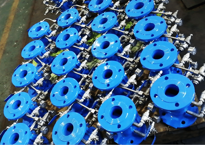
Judberd is competitive china manufacturer for different hydraulic control valve, we have Pressure Reducing Valves (PRV), Pressure Sustaining & Relief Valves, Flow Control Valves, Level Control / Float Valves, Slow Closing Check Valve, Pump Control Valves, Smart Pressure Management Valves as below.
Regulate Pressure Types
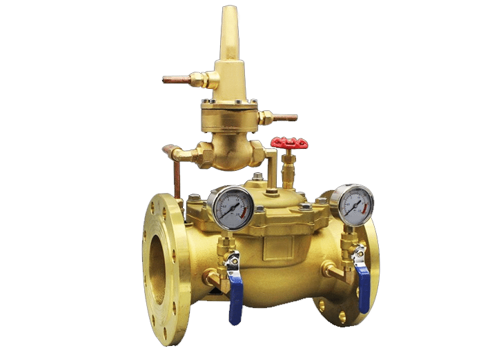
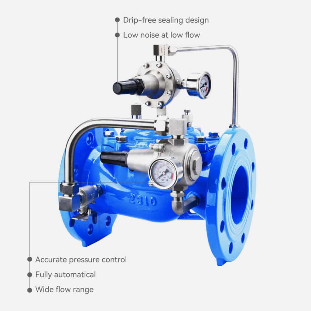
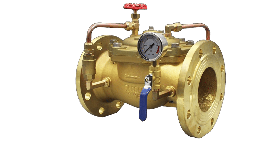
Pressure Reducing Valves (PRV)
Judberd Pressure Reducing Valves include Direct Acting Pressure Reducing Valve, Pilot Operated Pressure Reducing Valve, Full-Flow Pressure Reducing Valve, Low-Flow Bypass PRV, Threaded or Flanged PRV Options.
We have ductile iron, stainless steel and brass material types.It is designed to automatically reduce high upstream pressure to a stable, preset downstream pressure, ensuring a safe and reliable water supply system.
Below design is for your reference.

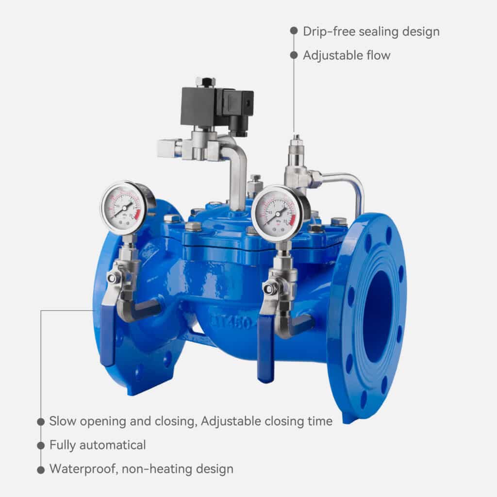
Flanged Full-Flow Direct Acting Pressure Reducing Valve
Flanged Pilot Operated Low-Flow Bypass Pressure Reducing Valve
Full-flow Threaded Branch Pressure Reducing Valve
Pressure Sustaining & Relief Valves
Judberd Pressure Relief and sustaining Valve can used for both function, When used as a pressure relief valve, it keeps the pipeline pressure below the preset safety value. When used as a pressure sustaining valve, it maintains the upstream pressure of the main valve above the preset value to ensure stable upstream supply pressure.
This valve is a hydraulically operated, pilot-controlled diaphragm valve. Judberd Pressure Relief & Sustaining Valves are available in ductile iron, stainless steel, and brass/bronze materials. The design below is for your reference.
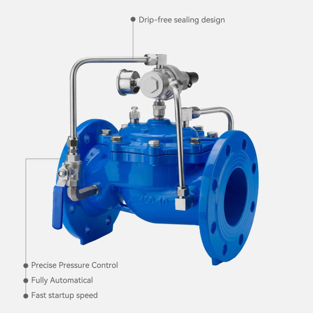
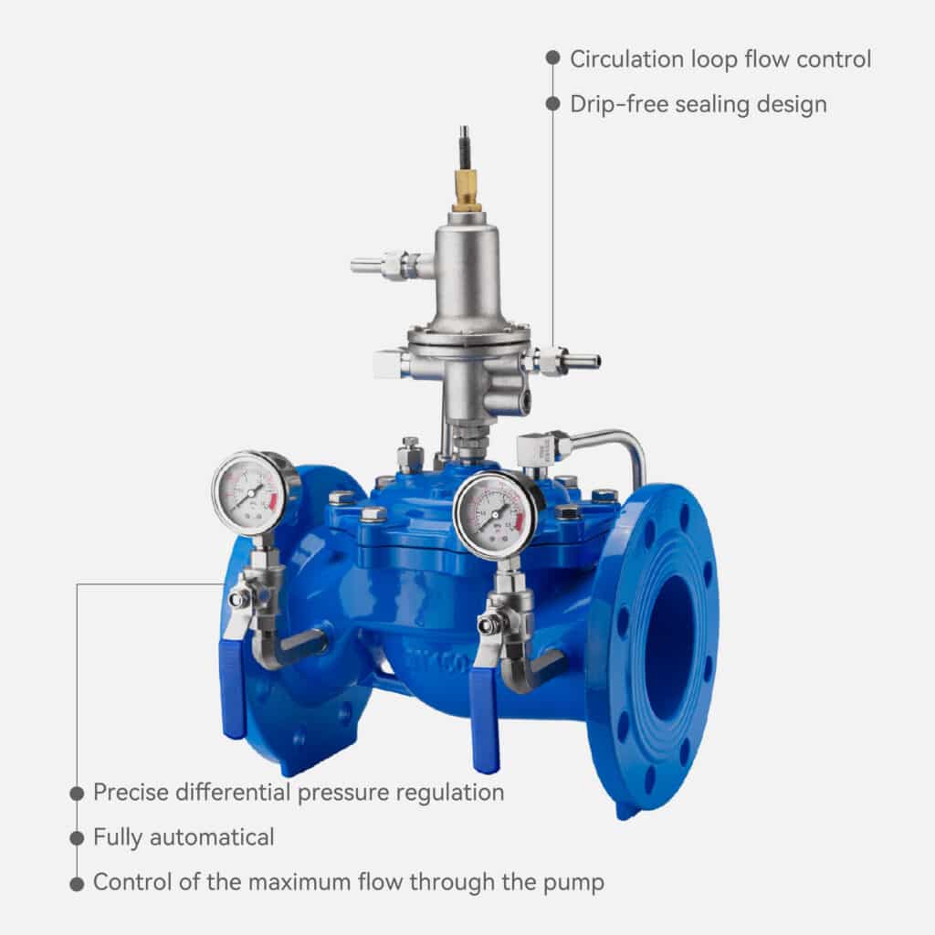
Pressure Relief Valve and Pressure Sustaining Valve
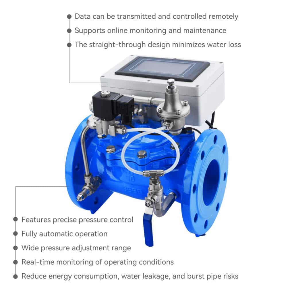
Smart Pressure Management Valves
The Judberd smart pressure management valve is an intelligent hydraulic control valve with pressure reducing and flow regulating functions. It is used not only in applications that require simple pressure reduction, but also in areas with severe leakage or in DMA district management zones.
It consists of six main components: the hydraulic main control valve, pressure reducing pilot valve, lithium battery, pressure sensor, 4G IoT transmission module, and control system.
Diaphragm Electric Control Valve
Electric control valve is an automatic hydraulic valve equipped with a pilot solenoid valve.
By receiving simple electrical signals, it can remotely open or close the pipeline, providing fast response, accurate pressure control, and stable system operation.
It is widely used in municipal water networks, pump stations, and building water supply systems that require intelligent and reliable automation.
Differential Pressure Control Valve
The Judberd differential pressure control valve consists of a hydraulic automatic main valve and a pilot-operated differential pressure balancing valve. It is a commonly used pressure control valve, mainly applied in central air conditioning condenser water systems. It is installed between the supply and return water lines to maintain a stable differential pressure.
By using the medium pressure and the pilot valve, the valve opening is automatically adjusted to keep the pressure difference between the supply and return pipelines constant.
This is a hydraulically operated, pilot-controlled diaphragm valve.
Flow Operation
Flow Control Valves
Judberd flow control valve that limits the flow rate to the maximum setting, regardless of changes in line pressure.The pilot control valve senses the differential pressure created across the orifice plate installed downstream of the valve. Any change in this differential pressure causes the main valve to react immediately, providing precise flow control.
To adjust the flow, turn the adjusting screw on the pilot control valve.This valve is a hydraulically operated, pilot-controlled diaphragm valve.
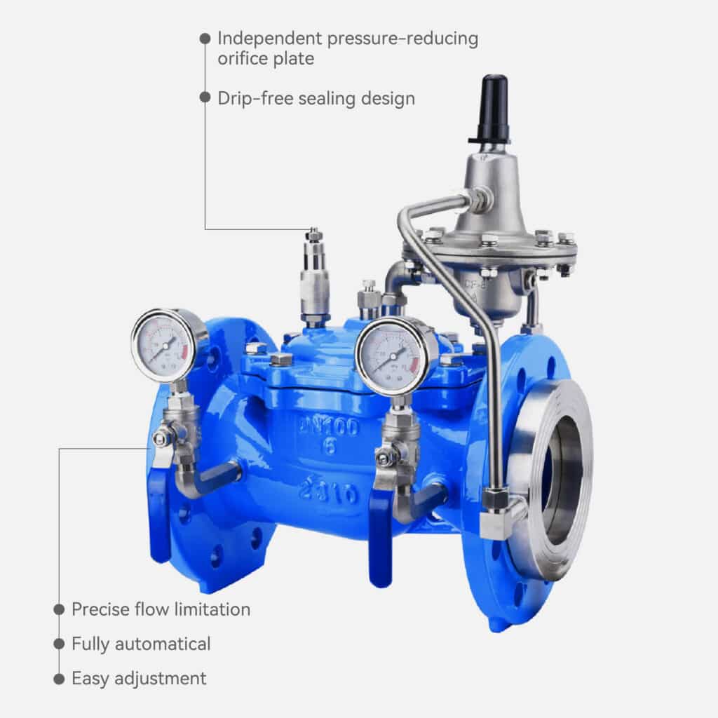
Judberd can offer ductile iron, stainless steel or brass/bronze material type, below our design is for your reference.
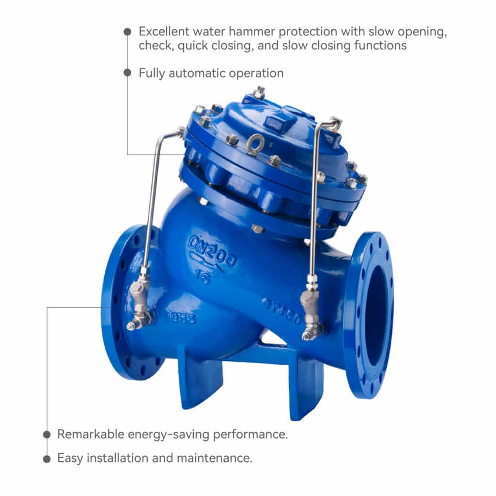
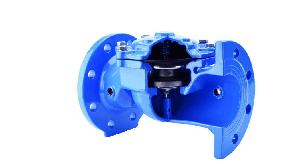
Slow Closing Check Valve
When water enters from the inlet side, it flows through the needle valve into the main valve’s control chamber. Water inside the control chamber then flows out through the double check pilot valve and the ball valve. Because the pressure in the control chamber is low, the main valve remains fully open.
When the pump stops supplying water, the water in the control chamber can no longer discharge. The control chamber pressure increases, pushing the diaphragm assembly downward to close the main valve.This valve is a hydraulically operated, pilot-controlled diaphragm valve.
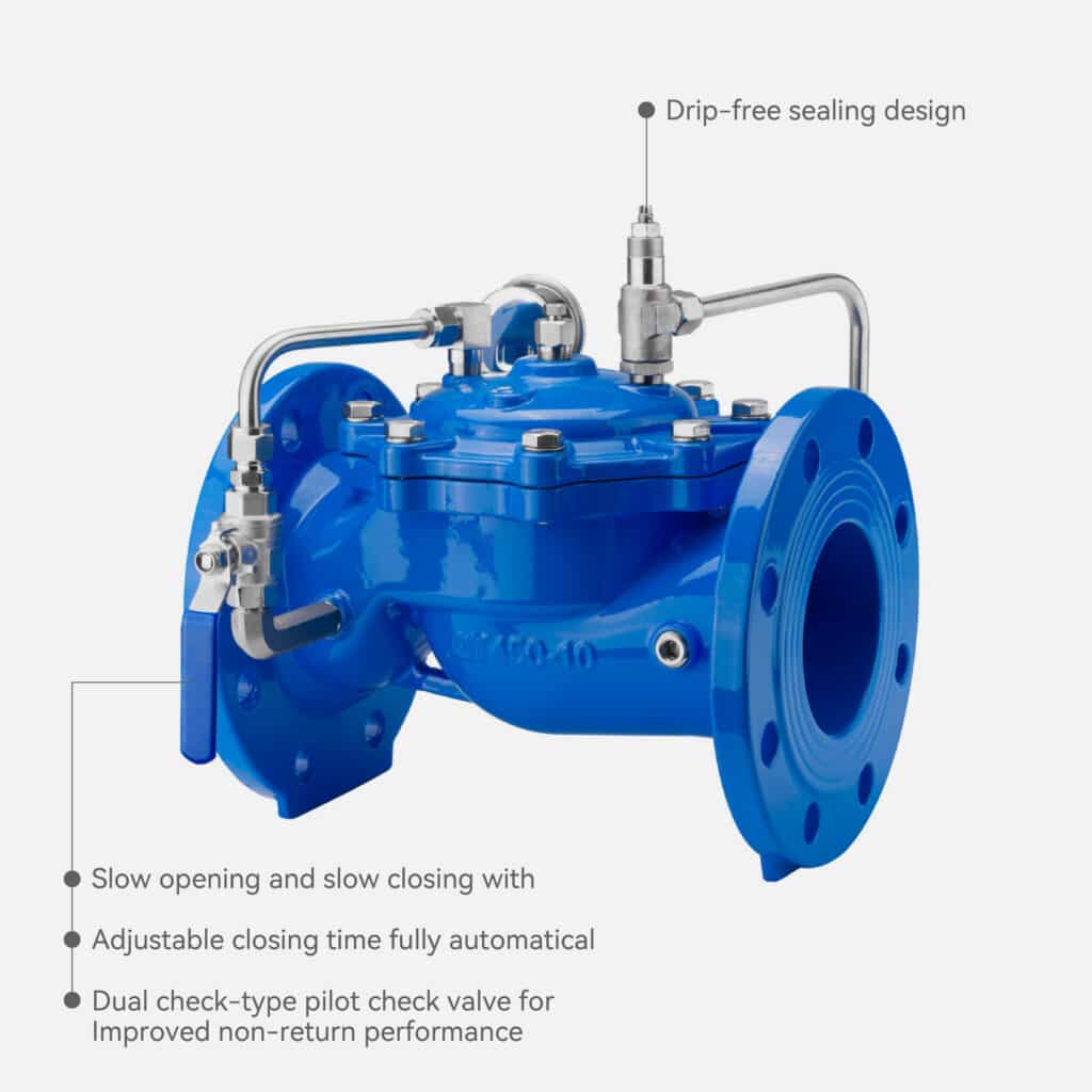
Judberd have ductile iron, stainless steel and brass/bronze material slow closing check valve, below our design is for your reference.
Level Operation
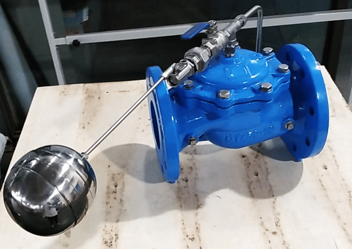
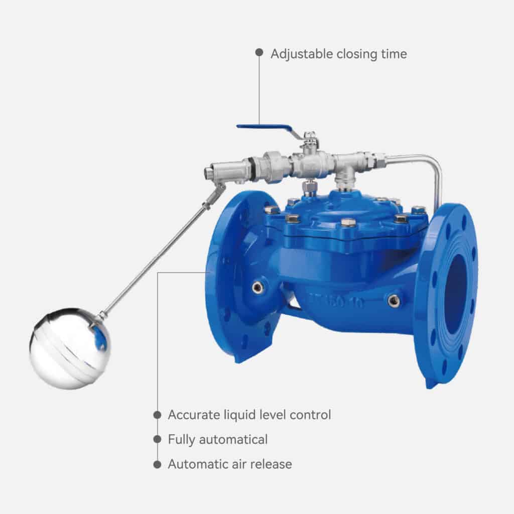
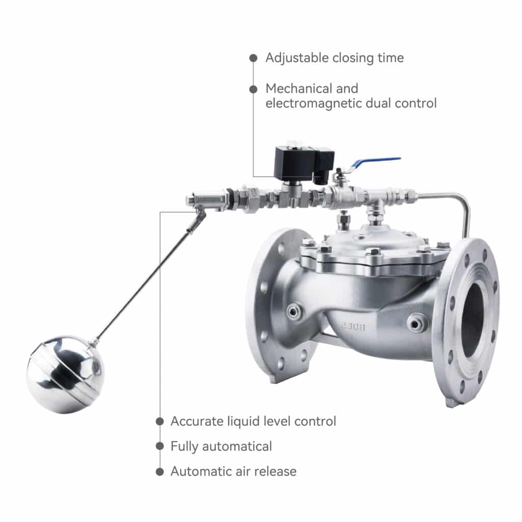
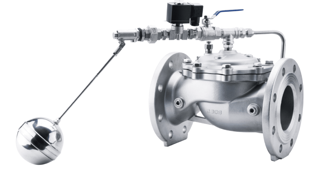
Float Valve
Judberd offers two types of remote float valves.
The first type is the hydraulic remote float valve, which consists of a main valve, needle valve, ball valve, float pilot valve, micro-filter, and other hydraulic control piping components. Once adjusted, it automatically controls the liquid level. This valve uses the liquid level directly for control, requiring no additional devices or energy. It is easy to maintain, provides high accuracy in liquid level control, is not affected by water pressure, and ensures reliable sealing.
The second type is the electric remote float valve, which can automatically compensate the tank volume according to supply and demand changes, keeping the liquid level stable. A pilot-type float sub-valve installed inside the tank determines the required liquid level. When the liquid level rises or falls, the main valve opens or closes accordingly. With both mechanical and electromagnetic control, it provides dual safety protection and higher reliability.
This valve is a hydraulically operated, pilot-controlled diaphragm valve.
Pump Operation
Pump Control Valve
The working principle of the Judberd Multifunction Pump Control Valve is as follows:
When the pump starts, the water pressure acts on the bottom of the main valve disc and the lower chamber of the control chamber, causing the main valve to open. The water in the upper chamber of the control chamber is slowly discharged to the outlet side through the regulating valve, allowing the main valve to open gradually. By adjusting the opening of the regulating valve, you can achieve an appropriate opening speed of the main valve.
When the pump stops, the inlet pressure drops rapidly. Under the combined effect of the valve’s own weight and the spring force, the valve quickly closes most of its opening to prevent backflow. The remaining opening is then slowly closed by the combined pressure from the upper and lower chambers of the control chamber. The slower closing speed creates a cushioning effect, preventing a sudden increase in pressure.
This valve is mainly used at pump outlets in municipal water systems, buildings, waterworks, and irrigation applications.
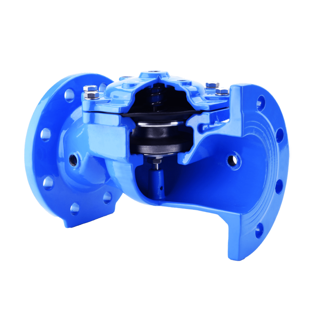
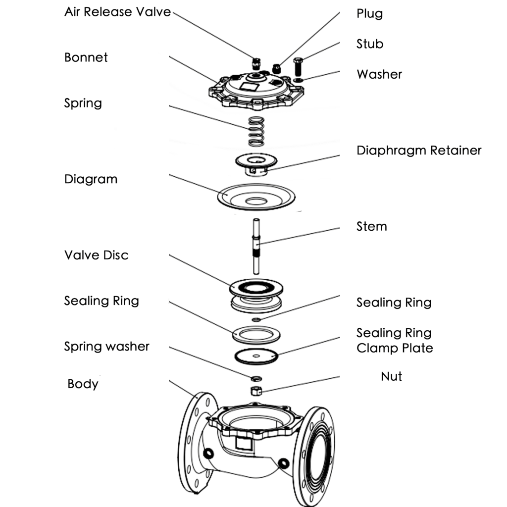
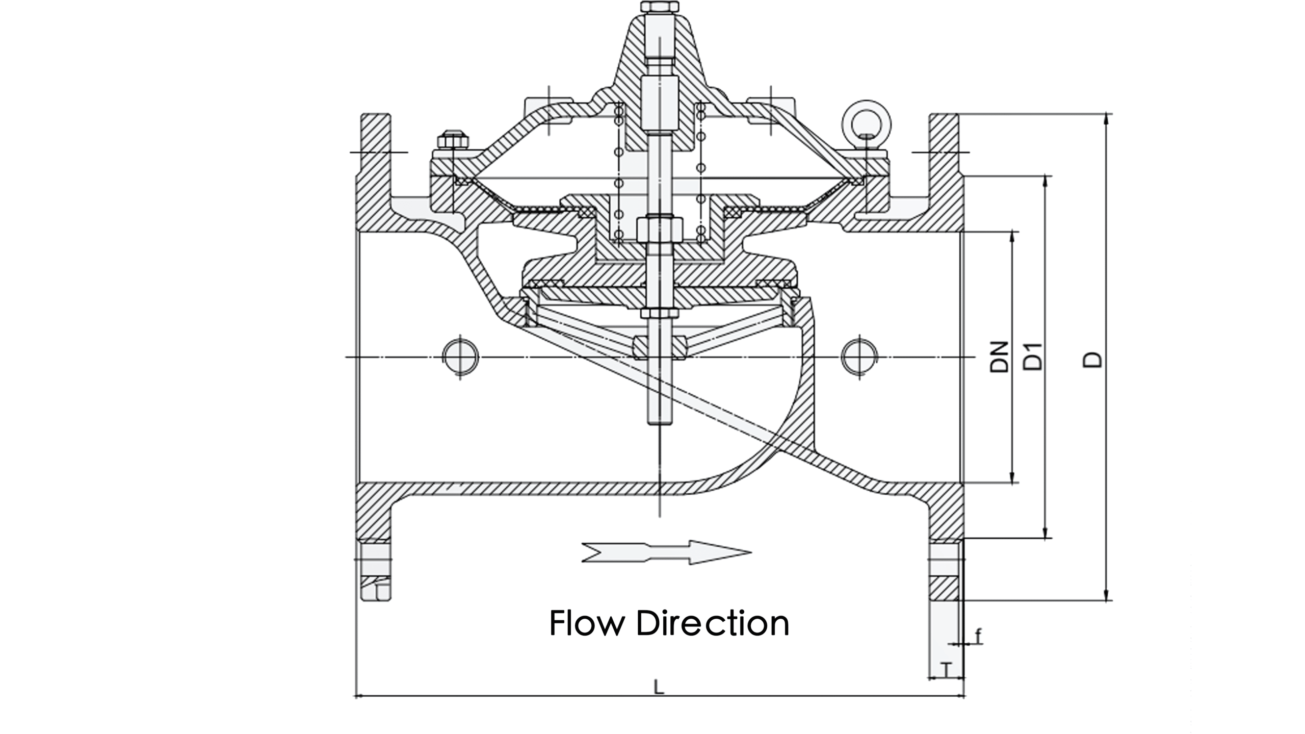
Main Valve Structure
The body of the Judberd Hydraulic Control Valve is composed of several key components, including the body/bonnet, disc/retainer, diaphragm, sealing ring, stem, spring, and others. Below are the photos and drawings for reference.
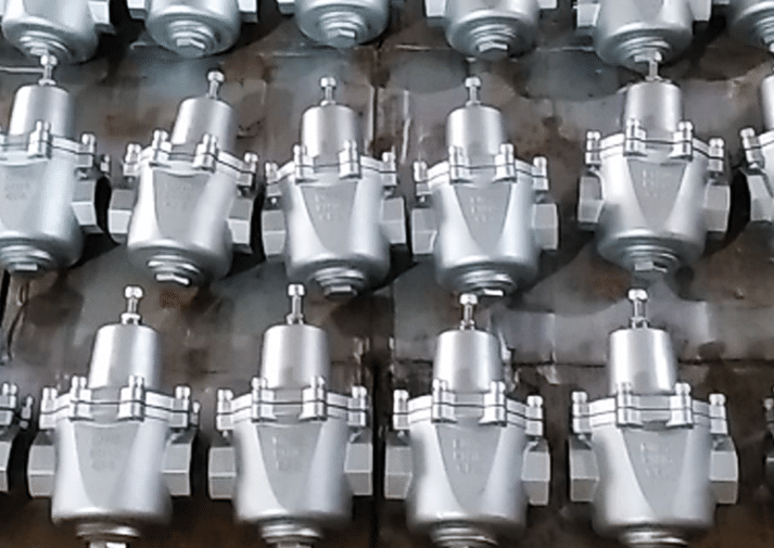
Material
Judberd hydraulic control valve material can be Ductile Iron, Stainless Steel or Brass/Bronze. The external components connected to the main valve body can be made of stainless steel or brass.
Below photos are for your reference.
Ductile Iron
Stainless Steel
Brass
Material for Each Part
| Part Name | Material | ||
|---|---|---|---|
| Body/Cover | Ductile Iron | Brass | Stainless Steel |
| Disc/ Diaphragm Retainer | Ductile Iron | Brass | Stainless Steel |
| Diaphragm | Reinforced nylon + EPDM rubber | Reinforced nylon + EPDM rubber | Reinforced nylon + EPDM rubber |
| Sealing Ring | NBR/EPDM | NBR/EPDM | NBR/EPDM |
| Disc | SS304/Brass | SS304/Brass | SS304/Brass |
| Spring | SS304/Brass | SS304/Brass | SS304/Brass |
| Bolts/Nuts | SS304/Brass | SS304/Brass | SS304/Brass |
Drawing
Dimension
| DN | D1 | D2 | D3 | N/ Φ d | L | ||||
|---|---|---|---|---|---|---|---|---|---|
| 1.0Mpa | 1.6Mpa | 1.0Mpa | 1.6Mpa | 1.0Mpa | 1.6Mpa | 1.0Mpa | 1.6Mpa | ||
| DN50 | 165 | 125 | 99 | 4- Φ 19 | 203 | ||||
| DN65 | 185 | 145 | 118 | 4- Φ 19 | 216 | ||||
| DN80 | 200 | 160 | 132 | 8- Φ 19 | 241 | ||||
| DN100 | 220 | 180 | 156 | 8- Φ 19 | 292 | ||||
| DN125 | 250 | 210 | 184 | 8- Φ 19 | 330 | ||||
| DN150 | 285 | 240 | 211 | 8- Φ 23 | 356 | ||||
| DN200 | 340 | 295 | 266 | 8- Φ 23 | 12- Φ 23 | 495 | |||
| DN250 | 395 | 405 | 350 | 355 | 319 | 12- Φ 23 | 12- Φ 28 | 622 | |
| DN300 | 445 | 460 | 400 | 410 | 370 | 12- Φ 23 | 12- Φ 28 | 698 |
Flow Rate
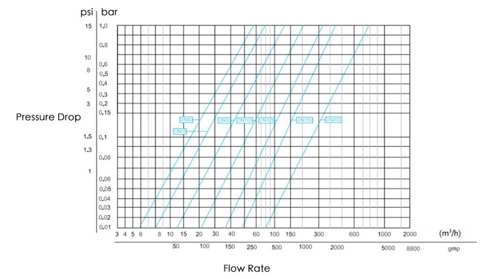
Full-Open Flow Rate Chart
The flow rate through a hydraulic control valve is directly influenced by the pressure drop (ΔP) across the valve and the valve opening position. Understanding this relationship is essential for proper valve selection, sizing, and system design.
1, Higher pressure drop lead to higher flow rate (valve fully open)
When the hydraulic control valve is fully open, Higher upstream pressure and lower downstream pressure create a larger pressure drop, a larger pressure drop provides more driving force for the flow. As a result, flow rate increases as pressure drop increases. 2, Valve Opening Changes the Pressure–Flow Relationship
Hydraulic control valves operate through a main valve and a pilot system that automatically adjusts the valve opening. When the valve closes, the flow area becomes smaller, pressure drop increases , flow decreases. When the valve opens , the flow area increases , pressure drop decreases , flow increases. So Flow rate depends on both ΔP and the valve opening position.
3, Engineering Formula: Flow Is Proportional to the Square Root of Pressure Drop
Like other control valves, hydraulic control valves follow the Cv equation:
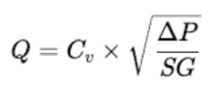
Q = Flow rate;Cv = Valve flow coefficient; ΔP = Pressure drop; SG = Specific gravity of the fluid (water ≈ 1)
This means: The relationship between flow and pressure drop is non-linear. To double the flow, the pressure drop must increase by four times.
4, Different Hydraulic Control Valves Have Different Pressure Drop Characteristics
Each valve type works differently:
Pressure Reducing Valve (PRV) Regulates opening to maintain a fixed outlet pressure; ΔP is determined by the setpoint.
Pressure Sustaining / Relief Valve Increases ΔP to hold upstream pressure.
Flow Control Valve (FCV) Maintains a constant flow; ΔP automatically adjusts according to demand.
Hydraulic Check Valve (Slow-Closing) Head loss varies with closing speed and internal structure.
Each type has its own flow-pressure curve.
5, In Practical Applications, Too Much or Too Little Pressure Drop Causes Problems
Excessive pressure drop will leads to high energy loss, noise and vibration and potential cavitation damage.
Insufficient pressure drop will lead to valve cannot regulate properly, poor stability, limited control range.
For most systems, engineers ensure a minimum working pressure drop of 0.1–0.3 MPa across the valve to guarantee stable and accurate performance.
Flow rate through a hydraulic control valve is determined by the pressure drop and the valve opening. Higher ΔP and larger opening produce higher flow. The flow–pressure relationship follows a square-root curve and varies by valve type and size.
Working Principle
Judberd hydraulic control valves operate automatically using water pressure, not electricity.They work based on two principles: Pressure balance on the diaphragm and The pilot valve guiding the main valve to open or close.
Step 1 — Water enters the valve Water enters the main valve body from the upstream pipeline.
Inside the valve are two key areas: The diaphragm chamber (upper area) and The flow chamber (lower area), The diaphragm controls whether the valve opens or closes.
Step 2 — The pilot valve decides the opening The pilot valve is the “brain” of the hydraulic control valve. It senses pressure, flow, or water level, and then it lets water into the diaphragm chamber or releases water out of the diaphragm chamber. Based on this, the main valve opens or closes automatically.
Step 3 — When the pilot sends water into the diaphragm chamber , the valve closes. When water pressure enters the upper diaphragm chamber, it pushes the diaphragm downward, pressing the disc toward the seat: 1)Diaphragm pushes down 2)Disc/plug closes 3)Main valve shuts or throttles. This happens because the upper chamber pressure is larger than lower chamber pressure.
Step 4 — When the pilot releases water from the diaphragm chamber , the valve opens.
When the pilot valve allows the water in the diaphragm chamber to escape, then 1) Pressure above the diaphragm drops 2) Upstream water pressure pushes the diaphragm upward 3) Disc/plug lifts 4) Main valve opens
The valve opens proportionally depending on how much pressure the pilot allows to remain.
The pilot valve is like a “traffic light”, the diaphragm is like a “gate” and the water pressure is the “power source”.
The pilot tells the diaphragm when to open and when to close. No electricity needed — only water pressure.
| Parts | Role | Function |
|---|---|---|
| Pilot Valve | The “controller” | decides opening/closing based on pressure/flow/level. |
| Diaphragm | The “heart” of the main valve | moves up/down to control flow. |
| Valve Disc / Plug | Physically blocks or allows water to pass. | |
| Needle Valve (Throttle Valve) | Adjusts response speed; stabilizes the system. | |
| Ball Valves | Used to isolate or control pilot lines during setup. | |
| Tubing (Copper/Stainless) | Connects pilot system to diaphragm chamber; transmits pressure. |
These parts work together to achieve automatic, stable, and precise control.
Judberd hydraulic control valve uses water pressure to automatically open or close.
The pilot valve adjusts the pressure above the diaphragm, and the diaphragm moves the main valve disc to control flow, pressure, or level.