Jacking Pipe Manufacturer
Jacking pipe is a specially designed pipe used in pipe jacking construction methods. These pipes are engineered to withstand the high pushing forces applied by hydraulic jacks during underground installation, while maintaining their structural integrity and watertightness. They are built with high compressive strength and are often resistant to wear, corrosion, and environmental stresses.
Jacking pipes are commonly used in trenchless construction projects, such as for underground sewer systems, stormwater drainage, water supply lines, and industrial pipelines. Depending on the project requirements, jacking pipes can be made of reinforced concrete, steel, ductile iron, or high-strength plastics.
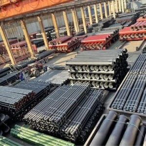
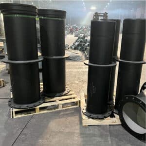
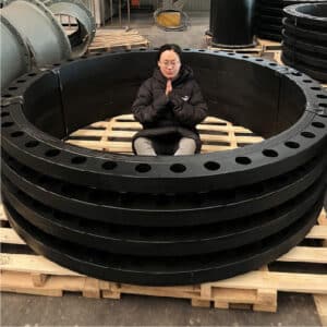
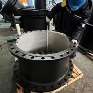
Judberd is china competitive manufacturer for ductile iron jacking pipes, below photos are for your reference.


What is Pipe Jacking?
Pipe jacking is a trenchless construction method used to install underground pipelines, ducts, and conduits without the need for large-scale surface excavation. It involves using powerful hydraulic jacks to push specially designed pipes through the ground from a launch shaft (thrust pit) to a receiving shaft, while excavation is carried out at the front of the pipe—usually within a protective shield or microtunneling machine.
Key Aspects of Pipe Jacking
Construction Method
_
● Pipes are pushed forward from the thrust pit using hydraulic jacks.
● Soil is excavated at the front either manually, mechanically, or by remote-controlled systems.
● Excavation and pipe advancement are done simultaneously to ensure safety and efficiency.
Main Equipment
_
● Hydraulic jacks: Provide the pushing force for the pipes.
● Jacking pipes: Specially reinforced pipes that can withstand high jacking forces.
● Shield or microtunneling machine: Guides the direction and supports the tunnel face.
● Lubrication system: Reduces friction between the pipe and surrounding soil.
● Guidance system: Ensures alignment and accuracy (e.g., laser-based control systems).
Construction Steps
_
● Build thrust pit and receiving pit.
● Install guide rails and hydraulic jacks in the thrust pit.
● Position the first jacking pipe and start excavation.
● Gradually push each pipe into the ground as soil is removed.
● Monitor direction, level, and jacking force throughout the process.
● Complete the drive when the pipe reaches the receiving shaft.
Technical Features
_
● Suitable for pipe diameters from 150 mm to over 3000 mm.
● Can achieve long drives—hundreds of meters in length.
● Minimal surface disruption, ideal for urban areas, roads, railways, rivers, and environmentally sensitive zones.
● Works in various ground conditions, including clay, sand, gravel, and rock.
Advantages of Pipe Jacking
No need for open trench excavation
Minimal impact on traffic and environment.
High precision in pipeline alignment.
Strong, watertight finished pipelines.
Reduced surface settlement and ground disturbance.
Pipe jacking is a highly efficient, accurate, and non-disruptive method of underground pipeline installation, widely used in municipal, industrial, and infrastructure projects.
Pipe Jacking Force Calculation
In a pipe jacking project, calculating the required jacking force is critical to ensure safe and smooth operation. Insufficient force may result in pipe blockage, while excessive force can damage the pipes or surrounding structures. The total jacking force depends on various factors, such as pipe length, diameter, weight, soil type, friction, and lubrication conditions.
1. Components of Jacking Force
_
The total jacking force (F) generally consists of:
F = F₁ + F₂ + F₃
F₁: Frictional resistance between the pipe outer surface and surrounding soil
F₂: Joint resistance between pipe segments
F₃: Cutting resistance at the front face (by shield or cutter head)
2. Simplified Jacking Force Formula
_
A commonly used empirical formula:
F = μ × q × L × π × D + F₀
Where:
F = Total jacking force (kN)
μ = Friction coefficient (depends on soil type and lubrication, typically 0.2–0.4)
q = Combined weight per meter of pipe and overburden pressure (kN/m)
L = Jacking length (m)
D = Outer diameter of pipe (m)
F₀ = Cutting resistance at the front (kN), often based on site experience
Note: Proper lubrication (e.g., with bentonite slurry) can significantly reduce friction (lower μ), thereby reducing jacking force.
3. Key Factors Affecting Jacking Force
_
Jacking length: Longer drives create more friction and require more force.
Soil type: Clay, sand, gravel, or rock have different friction and resistance characteristics.
Pipe material and surface: Smoother surfaces and well-lubricated pipes result in less friction.
Lubrication: Well-applied lubrication can significantly reduce jacking force.
Construction control: Alignment, speed, and steering accuracy all impact required force.
4. Example Calculation (Simplified)
_
Assume:
Jacking length (L) = 100 m
Pipe outer diameter (D) = 1.2 m
Weight per meter (q) = 10 kN/m
Friction coefficient (μ) = 0.3
Cutting resistance (F₀) = 300 kN
Calculation:
F = 0.3 × 10 × 100 × π × 1.2 + 300
≈ 0.3 × 10 × 100 × 3.14 × 1.2 + 300
≈ 1130 + 300 = 1430 kN
Accurate jacking force calculation is essential for a successful pipe jacking operation. It ensures proper equipment selection, safe installation, and minimal risk of pipe or ground failure. For detailed analysis, especially in complex projects, it’s recommended to use professional software and site-specific data combined with expert engineering judgment.
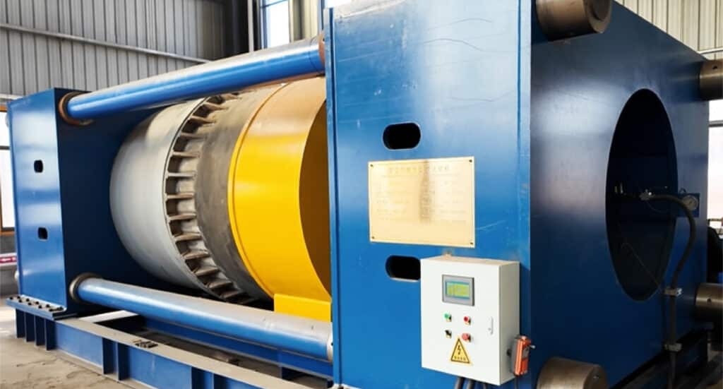
Jacking Force Test for DN2000 Pipe
Typical Applications for Jacking Pipes
Pipe jacking is ideal for installing underground pipelines in locations where traditional open-cut excavation is difficult or not allowed. Common application scenarios include:

Urban Areas
Congested cities with dense buildings and underground utilities

Traffic Zones
Roads, highways, railways, and airports where excavation would disrupt transport

Environmentally Sensitive Areas
Rivers, wetlands, and protected zones

High Water Table Areas
Locations with high groundwater levels requiring sealed construction

Industrial Zones
Factories or industrial parks needing pipeline installation without interrupting operations

Under Special Structures
Crossing beneath bridges, tunnels, or heritage sites without disturbing the surface
Pipe jacking provides a safe, efficient, and environmentally friendly method for underground construction in these complex environments.
Jacking Pipe Advantage and Limitations
Advantages of Jacking Pipe (Pipe Jacking Method)
1, No Need for Surface Excavation Ideal for congested urban areas, highways, bridges, and railways;Avoids disruption to roads, landscaping, and existing infrastructure.
2, Minimal Impact on Surroundings Reduces noise, dust, and traffic disturbance;Suitable for night-time or time-restricted construction zones.
3, Adaptable to Various Ground Conditions Can handle clay, sand, gravel, and even soft rock;Compatible with shields or mechanical cutting heads for complex geology.
4, High Precision and Sealing Uses laser or electronic guidance systems for accurate alignment;Provides strong, watertight joints ideal for sewage, water supply, and drainage systems.
5, Long-Distance, Continuous Installation Can push hundreds of meters or more in a single drive;Well-suited for deep installations or large-diameter pipes.
Limitations of Jacking Pipe
1, Sensitive to Ground Conditions Challenging in layers with large boulders or hard rock;Requires detailed geotechnical investigations before construction.
2, High Accuracy Required Demands skilled operators and advanced guidance systems;Misalignment can lead to pipe damage or project failure.
3, Higher Initial Cost Expensive machinery and specialized teams needed;Equipment setup and maintenance increase upfront costs.
4, Requires Launch and Reception Shafts Additional excavation and site planning needed;Shaft construction may be limited by space or local restrictions.
Economic Considerations: Jacking vs. Open-Cut
| Item | Pipe Jacking | Traditional Open-Cut |
|---|---|---|
| Surface Disruption | Minimal | Significant (may require road closures) |
| Best for | Deep, large-diameter, sensitive zones | Shallow trenches, open areas |
| Construction Time | Generally shorter (continuous operation) | Depends on weather, traffic, etc. |
| Initial Investment | High (equipment, skilled labor) | Lower (basic equipment) |
| Long-term Cost | Competitive (less road repair, faster work) | Can increase (restoration, delays) |
| Ground Condition Tolerance | Strong | Limited |
Conclusion
Pipe jacking is a highly precise, low-impact, and efficient underground installation method—especially suitable for urban areas, traffic zones, and environmentally sensitive sites. While the initial cost is higher, the total project cost can be lower due to reduced surface restoration, fewer delays, and minimal disruption.
Jacking Pipe – Sizes and Materials
1, Pipe Size Range (Diameter)
Pipe jacking technology supports a wide range of pipe diameters, depending on the project requirements and ground conditions:
Minimum Diameter: approx. 150 mm
Common Range: DN300 – DN3000
Large-Diameter Applications: can exceed DN3000 with advanced equipment
The selection of pipe diameter depends on the application (e.g., sewer, drainage, utility tunnel), hydraulic design, and allowable construction space.
2. Common Materials for Jacking Pipes
To ensure structural integrity, durability, and jacking resistance, different materials are selected based on project needs:
Material Features & Application
| Material | Features & Application |
|---|---|
| Reinforced Concrete (RCP) | Most widely used; high compressive strength; suitable for large diameters (DN600+) |
| Steel Pipe | High strength, flexible, suitable for long distances or complex alignments |
| Ductile Iron | Corrosion-resistant, strong, often used in pressurized water or sewer lines |
| HDPE (High-Density Polyethylene) | Light weight, corrosion-resistant, mainly for smaller diameters and short jacking lengths |
| GRP (Glass Reinforced Plastic) | High corrosion resistance; lightweight; suitable for specific chemical or wastewater conditions |
| PVC (Polyvinyl Chloride) | Occasionally used for small-diameter short drives; limited structural strength |
The pipe material must be able to withstand jacking forces, ground pressure, and environmental conditions (e.g. corrosion, groundwater, chemicals).
3. Material Selection Considerations
Jacking force resistance
Pipe wall thickness and joint design
Corrosion and chemical resistance
Installation depth and ground condition
Application type (sewage, stormwater, industrial fluids, etc.)
Pipe jacking supports a wide range of pipe sizes (from 150 mm to 3000 mm and beyond) and is compatible with various materials such as reinforced concrete, steel, ductile iron, HDPE, and more. The choice of material depends on the pipe’s structural requirements, environmental exposure, and the specific needs of the project.