Light Duty Dismantling Joint Installation
STEP 1
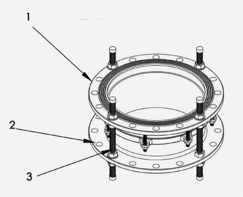
According to the design standard of the dismantling joint flanges at both ends(as below Fig No.1 and Fig No.2), the adjustable length range of the dismantling joint, the length requirement of the long bolts(as below Fig No.3), and the material requirement of each parts , to choose the correct dismantling joint.
STEP 2
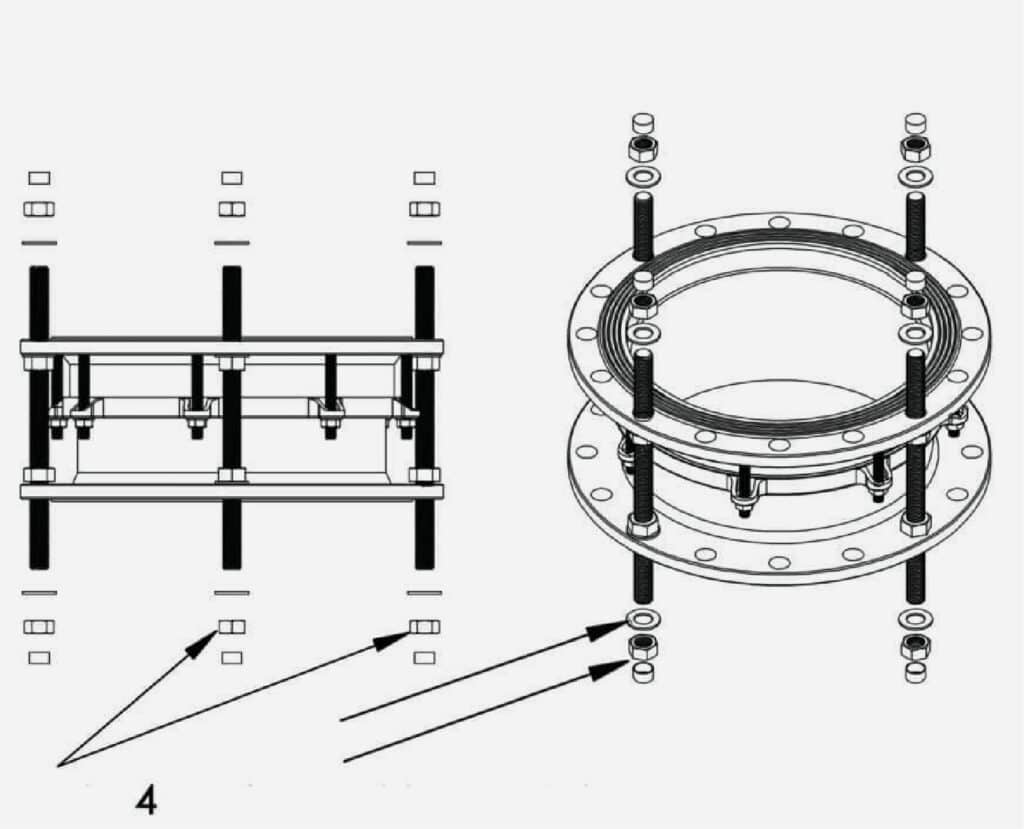
Disassemble all the nuts and washers(as below Fig No.4) at both ends of the dismantling joint.
STEP 3
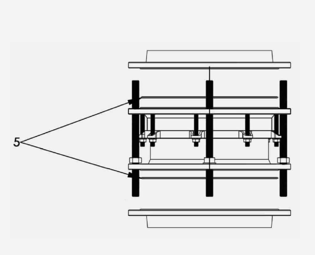
Select the matching flange gasket, align it with the flange face, and use a little glue to stick it on the flange sealing surface(as below Fig No.5).
STEP 4
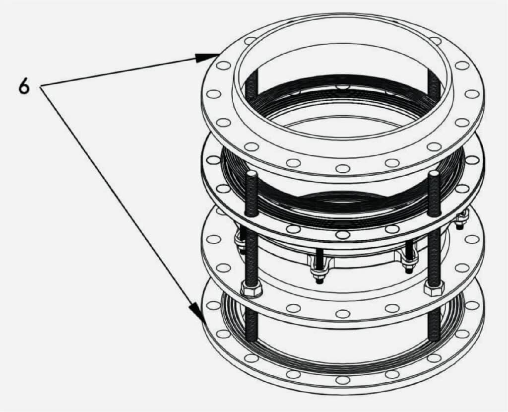
According to the design standard of the dismantling joint flanges at both ends(as below Fig No.1 and Fig No.2), the adjustable length range of the dismantling joint, the length requirement of the long bolts(as below Fig No.3), and the material requirement of each parts , to choose the correct dismantling joint.
STEP 5
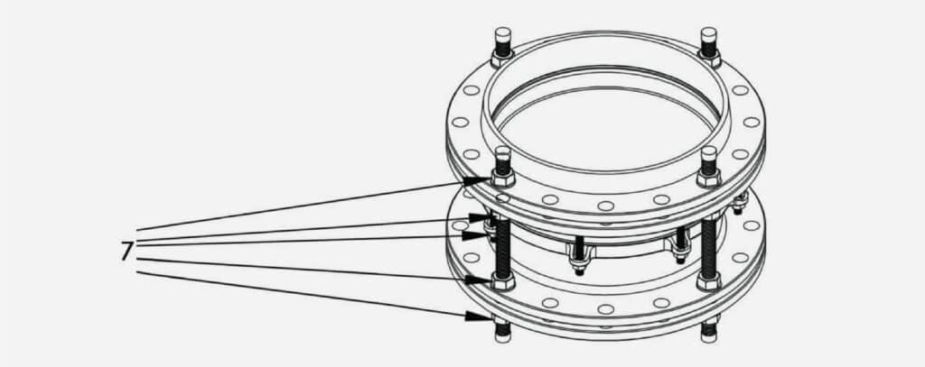
By adjusting the position of the following 5 nuts(as below Fig No.7), adjust the length of the dismantling joint to the needed length, and then in accordance with the order of the diagonal in turn, divided into a number of times uniformly tighten the 5 position nuts to the required torque. Test the dismantling joint with pressure in pipeline, requiring no leakage at 1.5 times of the working pressure. If there is any leakage, follow steps 1-5 above to check.


