Restrained Cast Iron Flange Adapter for PE Pipe Installation
Before installation, carefully check that the restrained flange adaptor for PE pipe is in good condition and that no parts are missing or damaged. Especially critical parts, such as the sealing gasket and grip ring, must be in perfect condition and the threads of the bolts must not be damaged in any way. It is also important to ensure that the restrained flange adaptor is selected to match the HDPE pipe to which it is to be connected. We have marked the outside diameter of the HDPE pipe to which the restrained flange adaptor can be connected on our end rings to avoid errors, and to ensure that the size of the flange of the restrained flange adaptor is correct. The dimensions of flange of the restrained flange adaptor must correspond to the flanges to be connected.
Step 1
Select a suitable restrained flange adaptor according to the outside diameter of the HDPE pipe, Judberd have marked the HDPE pipe outside diameter on our end ring.For example, for outside diameter 110mm PE pipe, we marked OD 110 on our restrained flange adaptor end rings.
Step 2
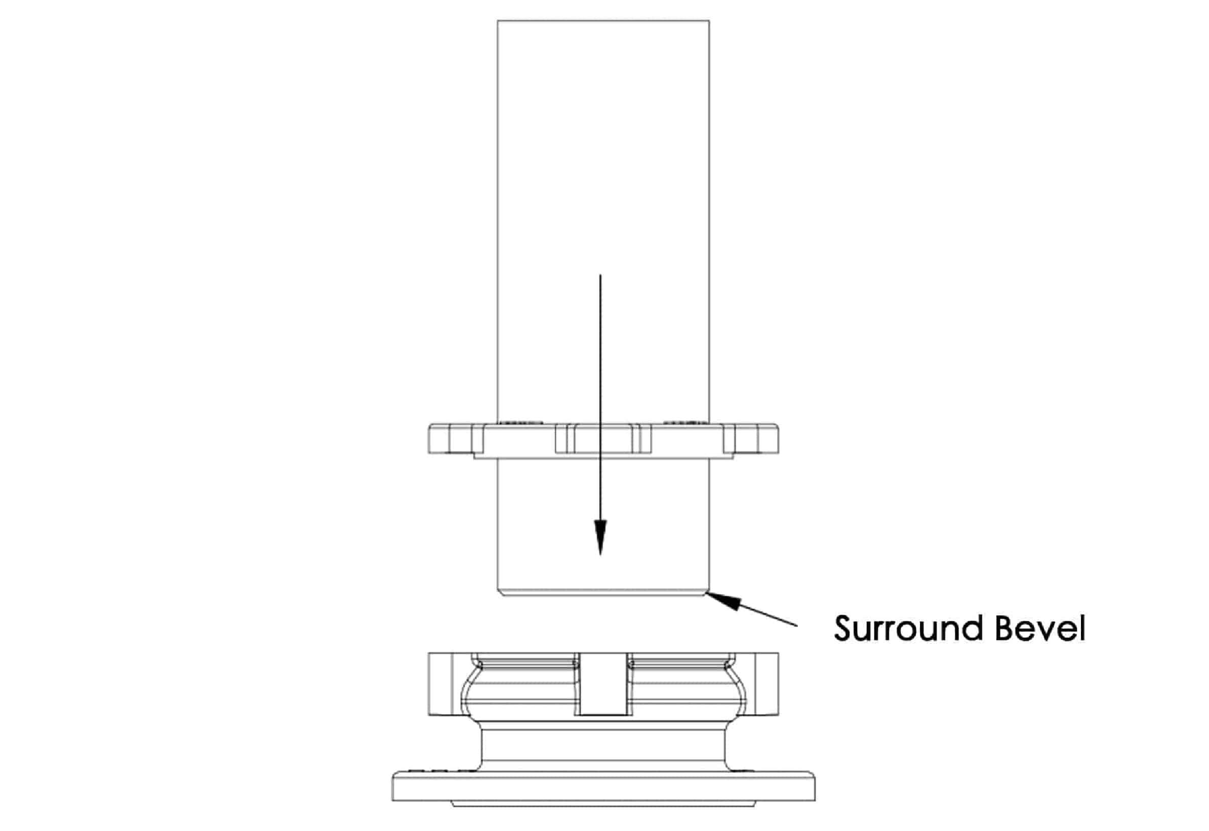
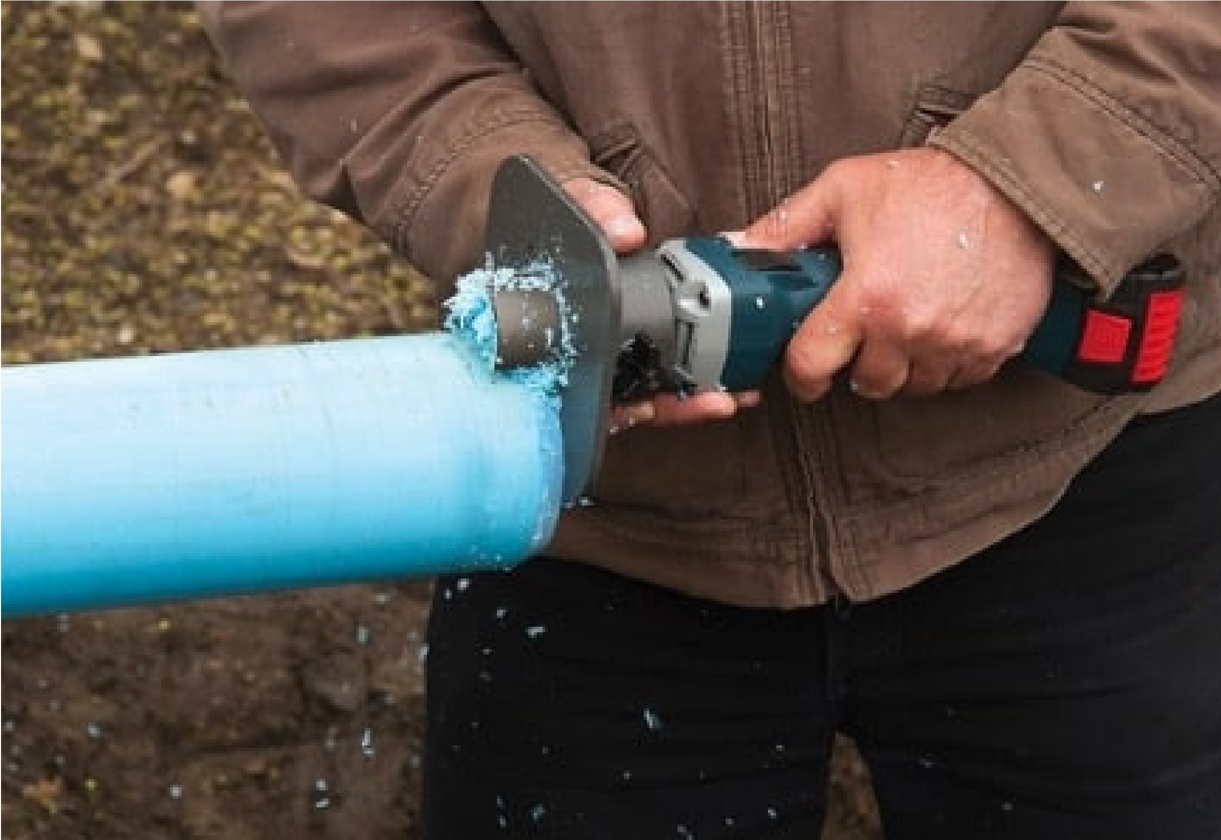
Bevel the end of the HDPE pipe which need to be insert to the flange adaptor, beveled pipe is easier to insert through the sealing rubber ring, then clean the HDPE pipe outside surface.


Step 3
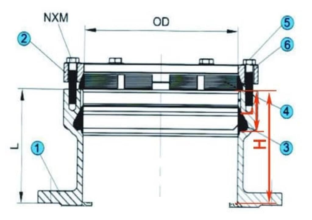
Disassemble the flange adaptor bolts (figure No.5 as below), measure the distance H from the upper plane of the flange body to the flange stopper, measure the distance L from the upper plane of the flange body to the bottom surface of the rubber ring, and mark the PE pipe to be connected with the distance L+10mm line from the end face of the pipe which need to be insert into the flange adaptor and the H line.

Step 4
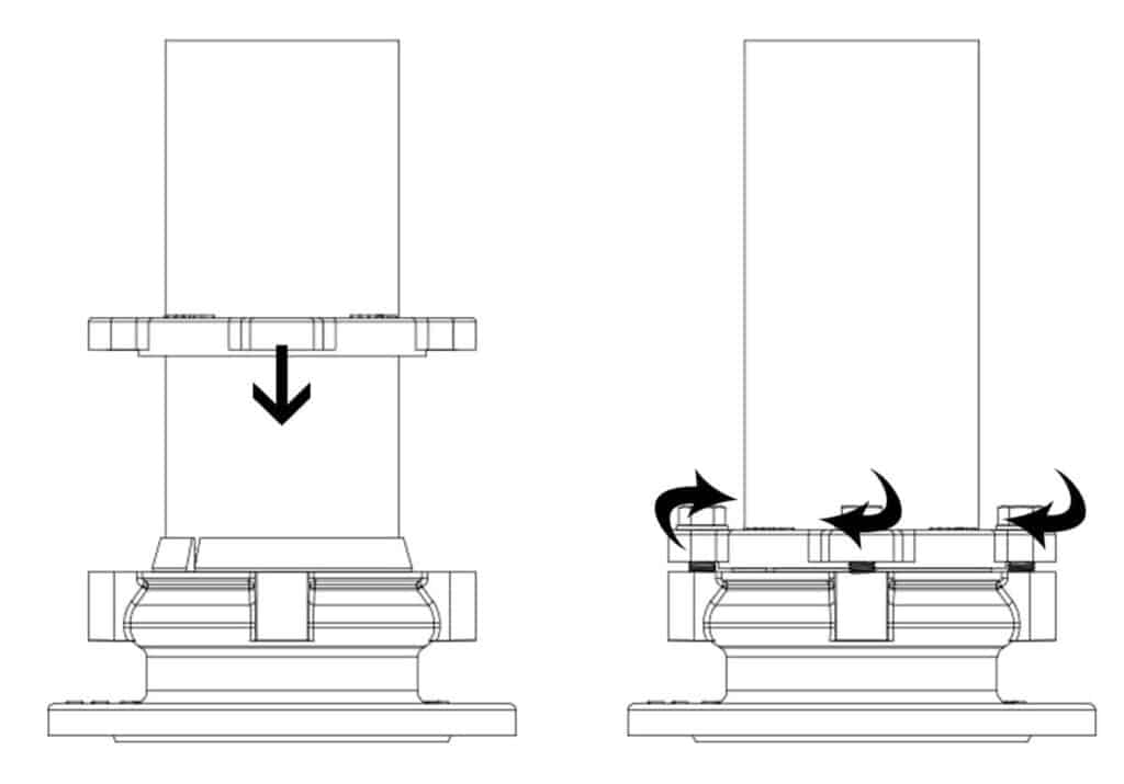
Put the grip ring(Figure No.4 as above) and disassembled gland (Figure No.2 as above)onto the PE pipe to be connected, insert the PE pipe into the inner cavity of the flange body(figure No.1 as above), let the PE pipe force through the rubber ring into the inner cavity of the flange so that the L+10mm line is inner than the upper plane of the flange body and the H line is out of the upper plane of the flange body.
Step 5
Hold the grip ring(Figure No.4 as above) to the pipe, let the gland( Figure No.2 as above) to hold the grip ring(Figure No.4 as above) downward the flange body(figure No.1 as above), rotate the bolt holes of the end ring aligned with the bolts holes of the flange body, screw on the bolts to connect, adjust all the bolts to uniform force, and then use the screwing spanner evenly tighten the bolts by diagonal turn to 25 N.m.

Step 6
Connect the flange of flange body to the flange of other piping element , slowly add the water pressure to observe whether the pipe is outwardly out, tighten the bolts(Figure No.5 as above) to increase the tightening force to 30 Nm if the pipe is outwardly out under pressure, then add the water pressure slowly to check.

