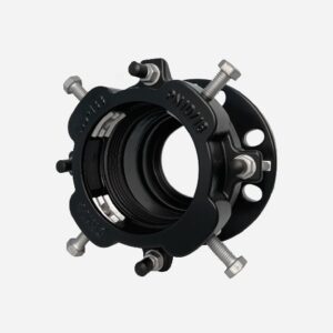
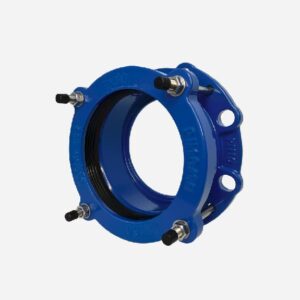
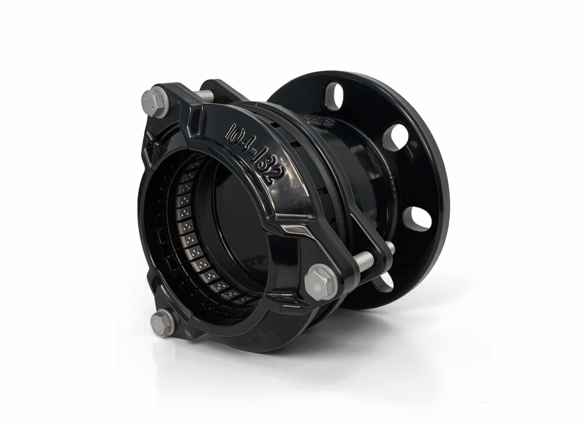
Aquagrip Flange Adaptor
The Aquagrip flange adaptor also called multigrip restrained flange adaptor or ultra grip flange adaptor, is a self-anchoring flange adaptor with a locking block at the socket end and is available in a wide range of sizes to allow the connection of different pipes. The flange adaptor has the advantage that the restrained flange adaptor can grip the pipe and prevent it from leaking due to deformation, while the universal flange adaptor can be used to connect a wide range of different pipes and thus reduce stock.
SPECIFICATION
● Aquagrip flange adaptor standard:comply with EN545
● Connection for pipes in material ductile iron, steel, PVC, PE, Stainless steel etc
● Mechanical locking by means of metal inserts in order to avoid pipe’s axial movement
● Working pressure PN10/16
● Flange drilling hole available for EN1092-2 PN10/16 , ASME B16.5 class150 and AS4087
● Maximum temperature -10℃ to +70℃
● Suitable for potable water, neutral liquids and sewage
● WRAS,ACS,DVGW,NSF approved
● Coating standard EN30677/EN14901
● Test standard EN12266-1
● Wide tolerance range
● Corrosion resistant construction
● Total angular deflection of ±4°
● Flange drilling with BS4505,EN1092-2 or ANSI Standard
● GD8.8, stainless steel bolts nuts and washers
● Various coating
● Seal:NBR etc
Precaution
Aquagrip flange adaptor can’t accommodate for AC(Asbestos cement) pipe and GRP pipe.Because AC pipe surface is too rough ,the griper of aquagrip flange adaptor can’t work properly.GRP pipe is very smooth, can’t offer enough friction for the griper.
OVERVIEW
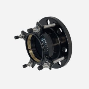
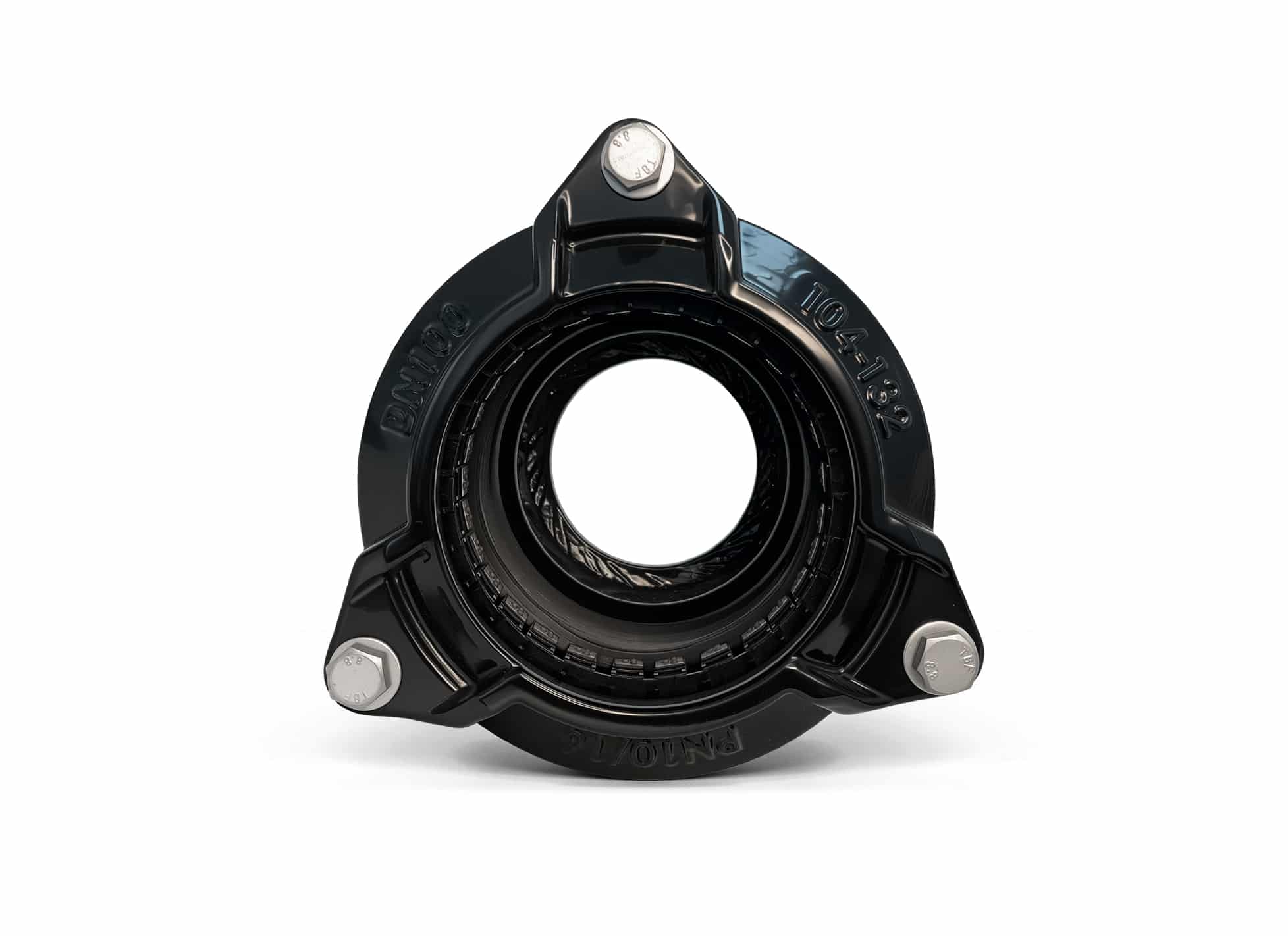
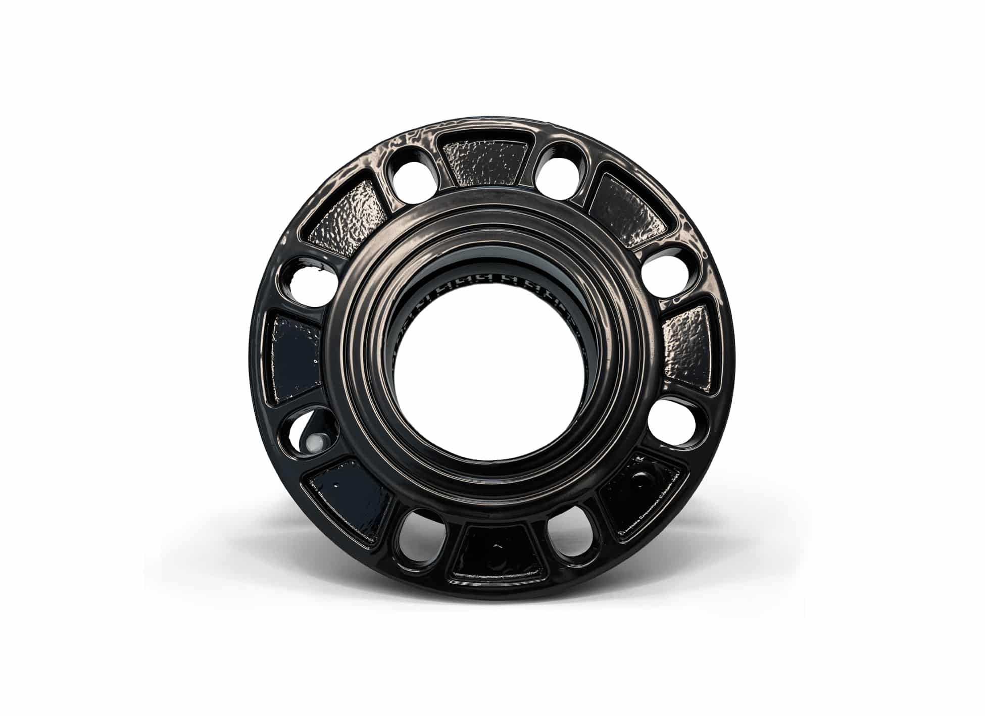
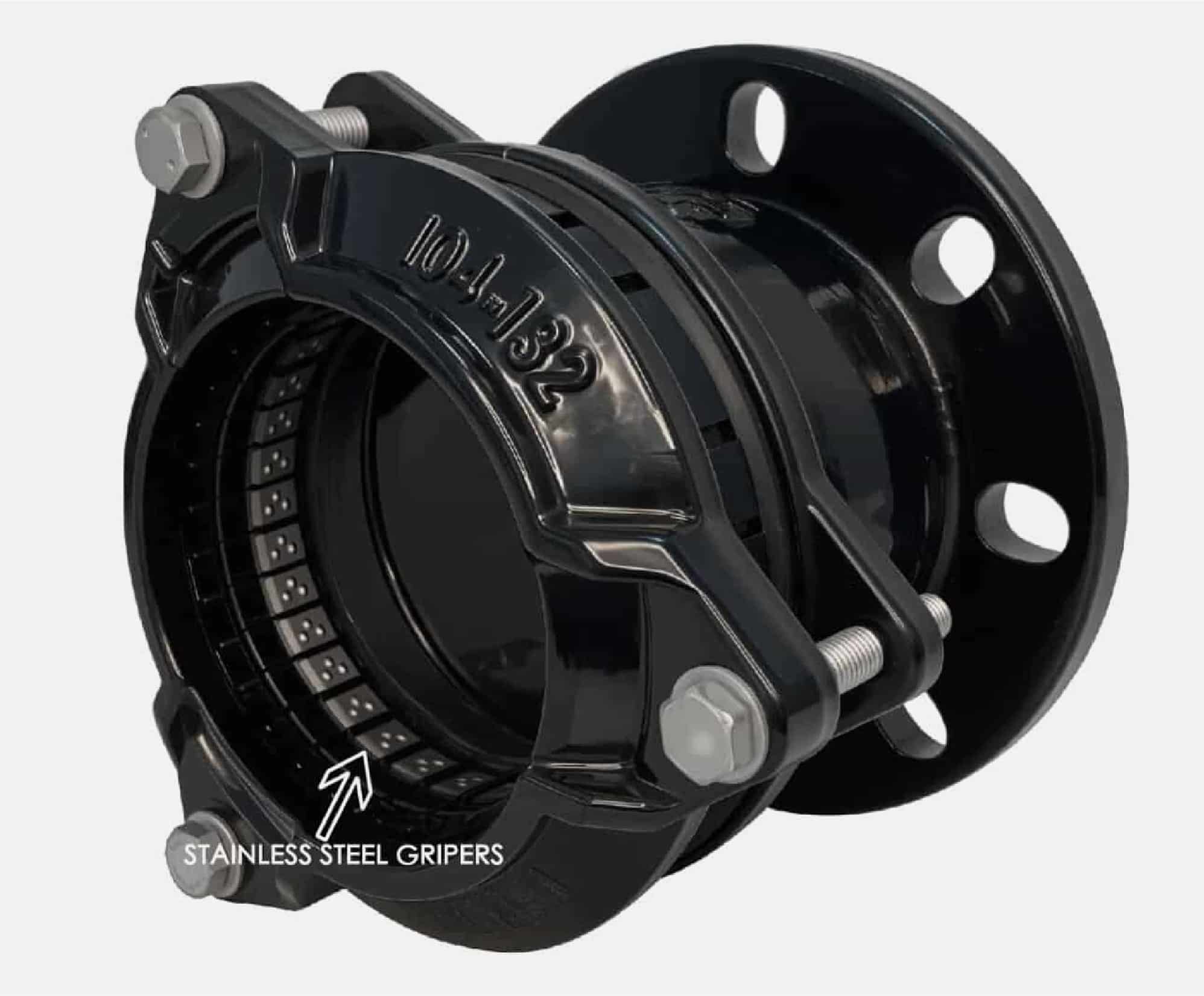
This flange adaptor is a product designed to connect flange end products to plain-end pipe , equipped with an axial anti-pull-out mechanism and excellent sealing performance. It can be used to connect pipes made of various materials, including ductile iron, grey cast iron, steel, PVC, and PE. This design specifically includes a locking mechanism for PE pipes — the tightening component (such as the stainless steel grip ring shown right) is detachable, allowing for easy removal and installation.
When connecting HDPE pipes, as long as the pipe is SDR ≥ 11, a stainless steel stiffener must be installed when using this flange adaptor — especially for thin-wall grades such as SDR17, 21, 26, 33, and 41. Even for SDR11, it is strongly recommended to install a stiffener under pressure or tension conditions.
The end rings are tightened with independent bolts, allowing better control of the tightening force. The force from the bolts is transmitted directly to a single gasket, making it easier to achieve a proper seal.
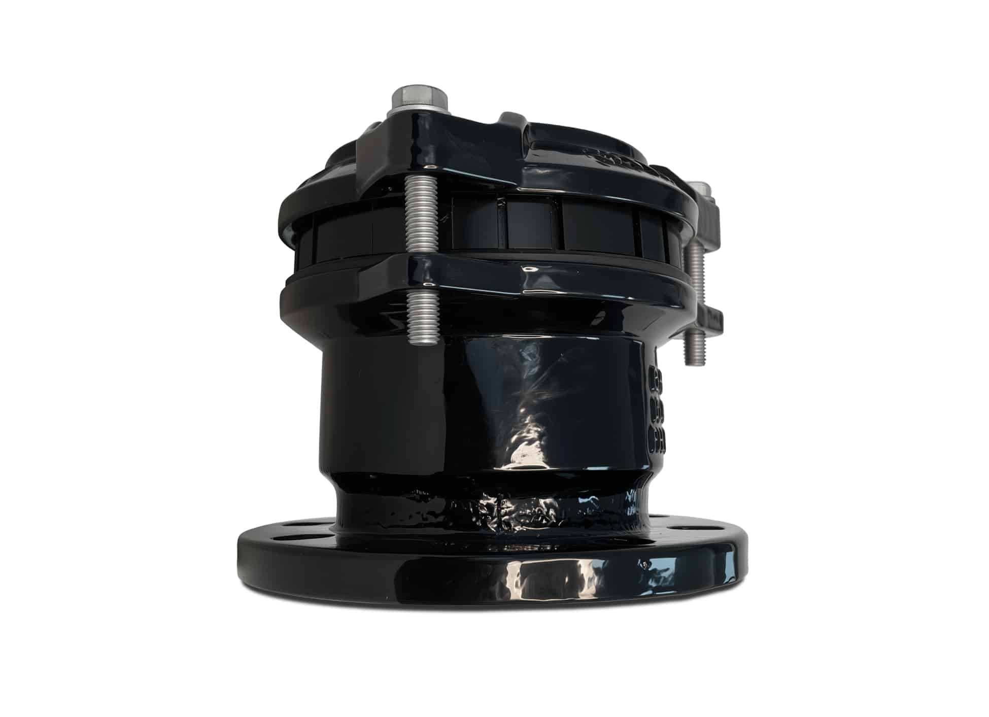
This product is easy to install. It is pre-assembled in our factory, so during actual use, you only need to insert the pipes into the appropriate depth of the flange adaptor and tighten the bolts to achieve secure and leak-proof connection. Due to its simple installation process, it is especially suitable for applications in confined spaces.
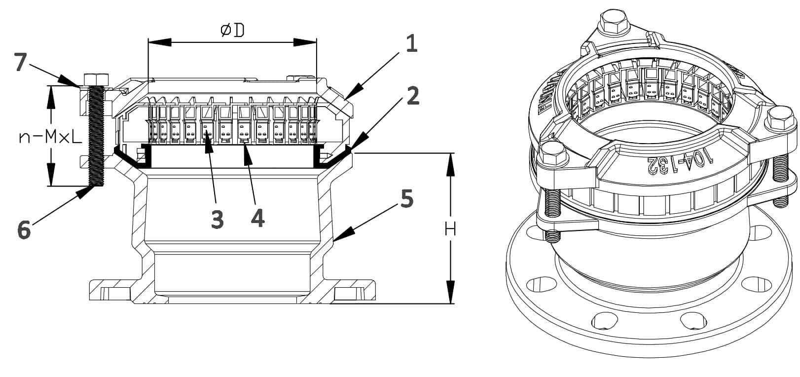
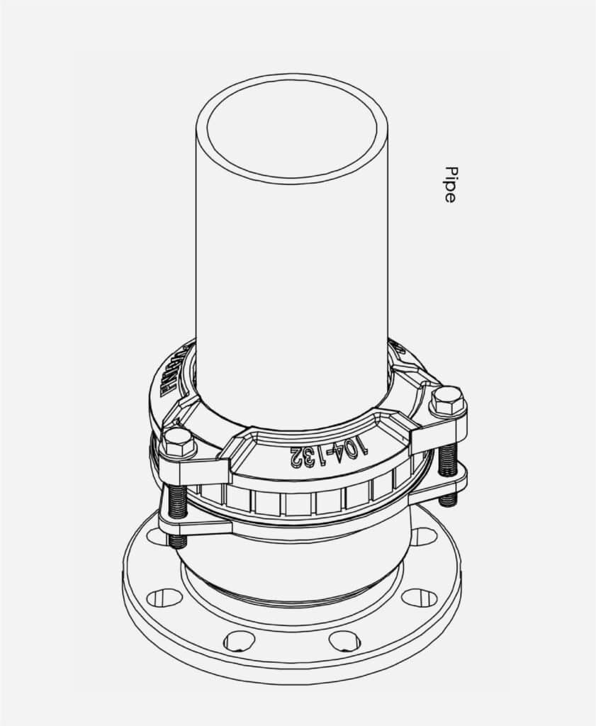
Drawing
Material
| Item No. | Parts | Material |
|---|---|---|
| 1 | End Rings | Ductile Iron EN GJS450-10 according to EN1563 |
| 2 | Gasket | EPDM Compound Grade E to BS EN 681-1 /Nitrile Compound to Grade G BS EN 682, Type G |
| 3 | Gripper | SS304 |
| 4 | Retractable Ring | POM(polyvinylchlorid) |
| 5 | Flange Body | Ductile Iron EN GJS450-10 according to EN1563 |
| 6 | Bolts | Grade 8.8 carbon steel or Stainless Steel |
| 7 | Washer | Grade 8.8 carbon steel or Stainless Steel |
| 8 | Coating | Rilsan Nylon 11 or FBE coating(Adhesion is not less than 12N/mm2) |
Dimension(unit:mm)
| DN | PN | RANGE | ∮D | H | n-MxL |
|---|---|---|---|---|---|
| 50 | PN10/16 | 46-71 | 73 | 120 | 3-M12x80 |
| 60/65 | PN10/16 | 63-90 | 92 | 120 | 3-M12x80 |
| 80 | PN10/16 | 84-105 | 107 | 120 | 3-M12x80 |
| 100 | PN10/16 | 104-132 | 134 | 120 | 3-M12x80 |
| 125 | PN10/16 | 132-155 | 157.5 | 130 | 3-M14x80 |
| 150 | PN10/16 | 154-192 | 194.5 | 130 | 3-M14x100 |
| 200 | PN10/16 | 192-232 | 235 | 150 | 4-M14x100 |
| 250 | PN10/16 | 267-310 | 313 | 150 | 4-M14x110 |
| 300 | PN10/16 | 315-356 | 359 | 160 | 6-M14x110 |
| 350 | PN10/16 | 352-393 | 396 | 160 | 6-M14x110 |
| 400 | PN10/16 | 392-433 | 436 | 170 | 8-M14x110 |
| 450 | PN10/16 | 450-482 | 485 | 170 | 8-M16x120 |
| 500 | PN10/16 | 500-532 | 535 | 180 | 8-M16x120 |
| 600 | PN10/16 | 605-637 | 640 | 180 | 8-M16x120 |
Installation Manual
Step 1
Select the appropriate size range of flange adaptor based on the outside diameter of the pipe to be connected. Ensure that the pipe material (Judberd’s Aquagrip Flange Adaptor is suitable for ductile iron, grey cast iron, steel, PVC, and PE pipes) and the working pressure match the adaptor specifications.
Before use, carefully inspect the appearance of the adaptor to ensure there is no damage, deformation, or corrosion. Pay special attention to the condition of the sealing ring and grip ring.
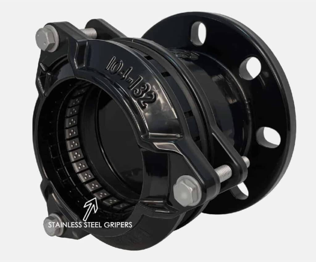
If connecting PE pipes, stainless steel grip segments (as shown right) must be included.
When connecting HDPE pipes, as long as the pipe is SDR ≥ 11, a stainless steel stiffener must be installed when using this adaptor — especially for thin-wall grades such as SDR17, 21, 26, 33, and 41. Even for SDR11, the use of a stiffener is strongly recommended under pressure or tension conditions.
If connecting pipes made of other materials, the stainless steel grip segments should be removed.
Step 2
Clean the pipe ends and the contact surface of the adaptor to ensure they are free of oil and debris, to ensure proper sealing.
Step 3
Connect the flange end of the Aquagrip Flange Adaptor to the mating flange of the pipeline system according to standard flange installation procedures. This typically involves flanged valves, water meters, or flanged fittings.
Step 4
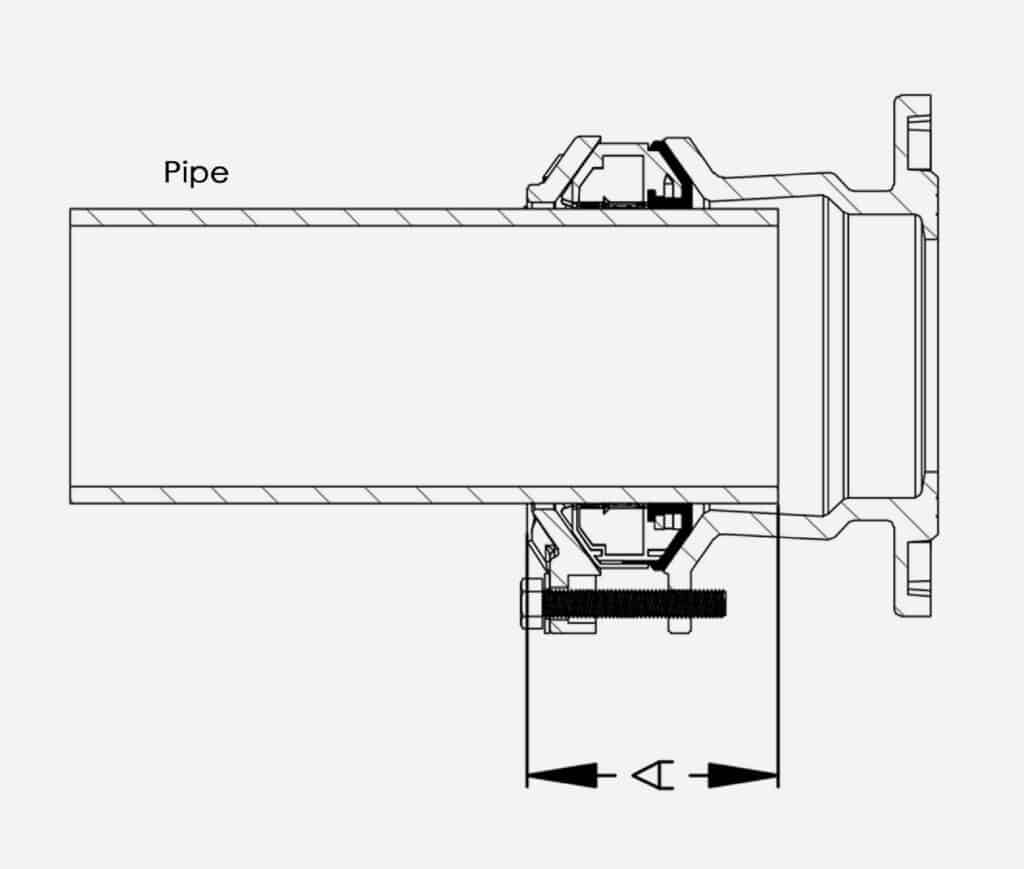
4-1. Judberd’s Aquagrip Flange Adaptor is pre-assembled. For actual use, simply insert the pipe into the adaptor to the appropriate depth (refer to Judberd’s technical specification sheet for recommended insertion depth), then tighten the bolts diagonally in multiple passes to the specified torque: 65–70 N·m.
This allows for easy connection and secure anti-pull-out locking. The simple installation process makes it especially suitable for use in confined spaces.
4-2. If the product is not pre-assembled, please follow the steps below for installation:
Disassemble all components (bolts, end ring, plastic grip segments, sealing ring, and flange body). Sequentially slide the components onto the pipe in the following order: end ring – plastic grip ring – sealing ring – flange body.
After sliding the grip segments on, adjust the spacing between the grip blocks to ensure even gaps. After adjustment, ensure the end ring and grip ring are perpendicular to the pipe.
Step 5
Use bolts to connect the end ring and flange body. Tighten the bolts diagonally in multiple passes evenly to the specified torque: 65–70 N·m.
Step 6
Perform a pressure test run, with the maximum pressure meeting 1.5 times the nominal pressure (1.5*PN). If there is any leakage or seepage, close the pressure, and repeat steps 1-6 as needed.