American flow control gate valve is Gate Valve which manufactured according to AWWA standard. The most commonly mentioned standards are AWWA C509 and AWWA C515. AWWA c515 is the latest standard and for valves made of ductile iron, AWWA C515 flange and valve wall thickness is a little thinner than AWWA C509.
Judberd can offer AWWA valves with flange ends, mechanical joint ends, socket ends, spigot ends and restrained joint ends for HDPE pipe.
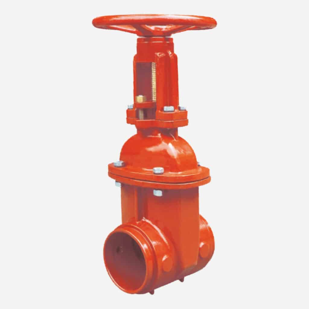
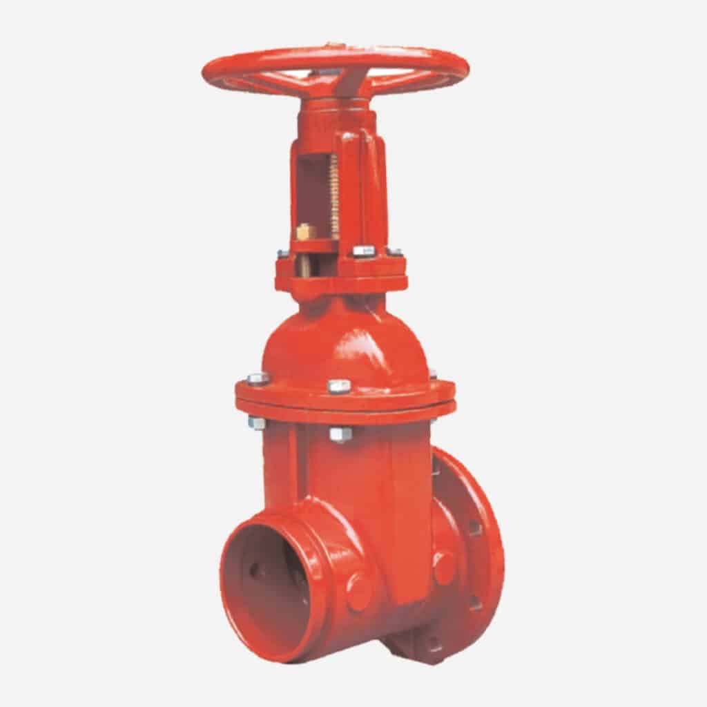
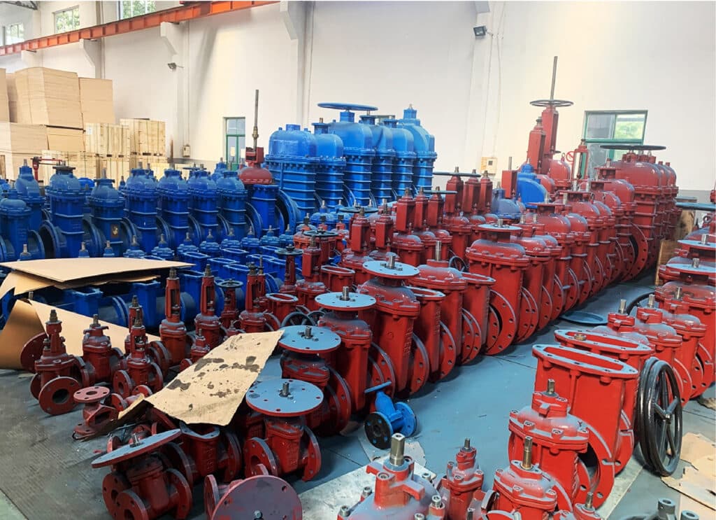
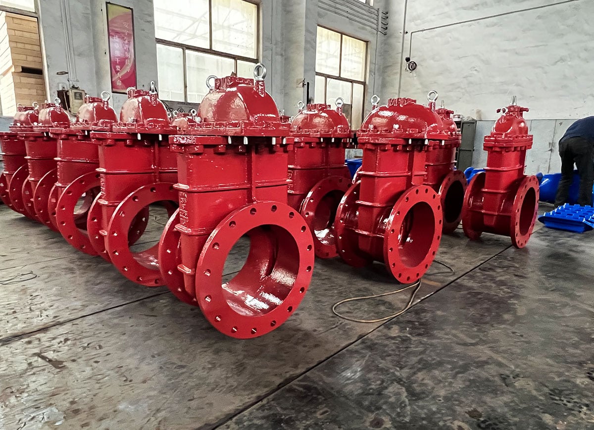
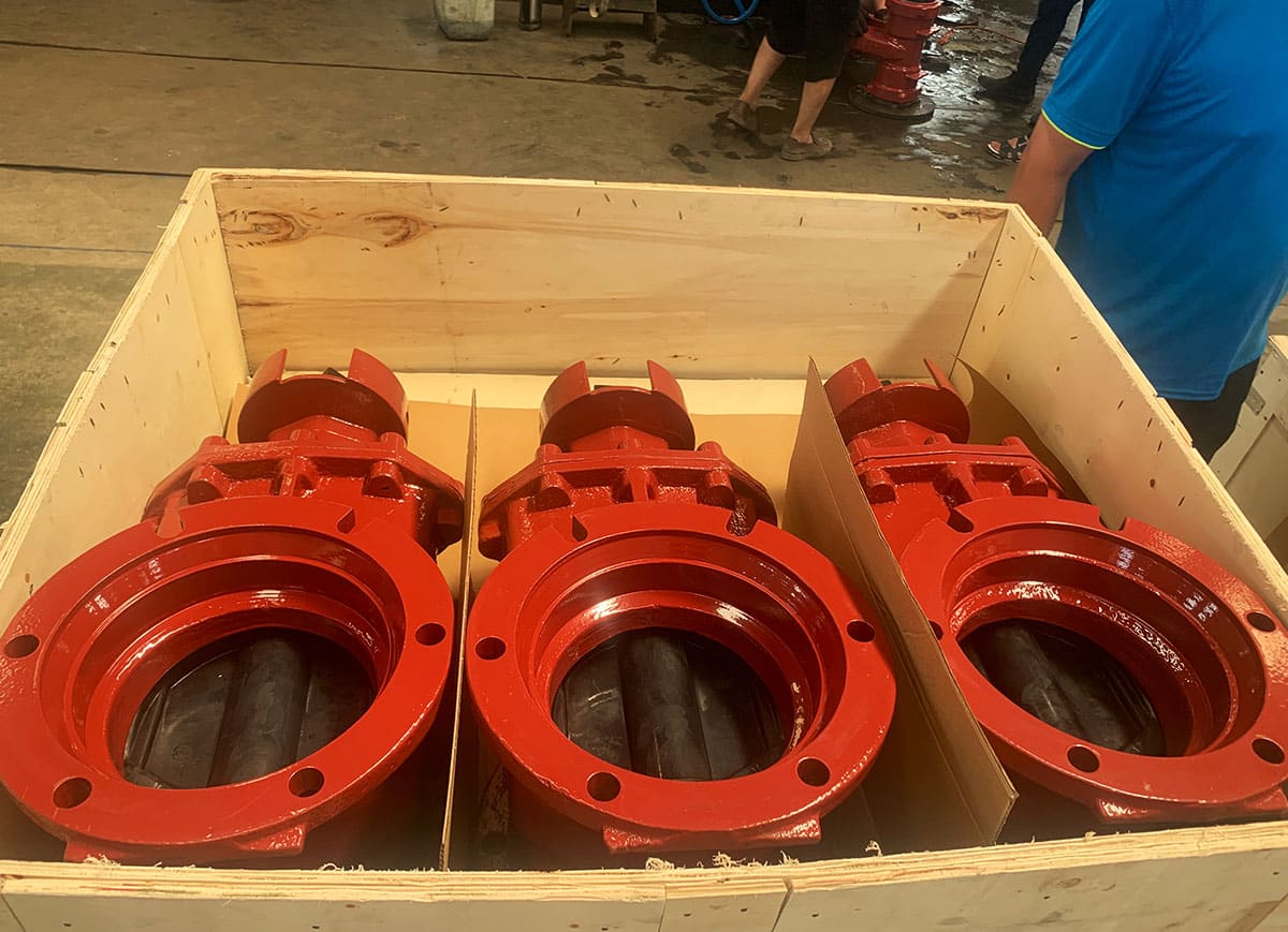
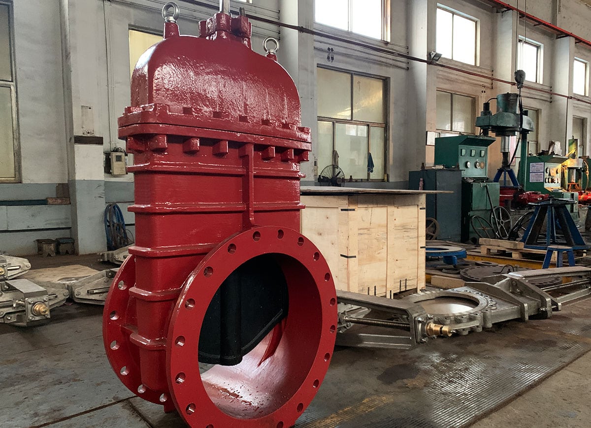
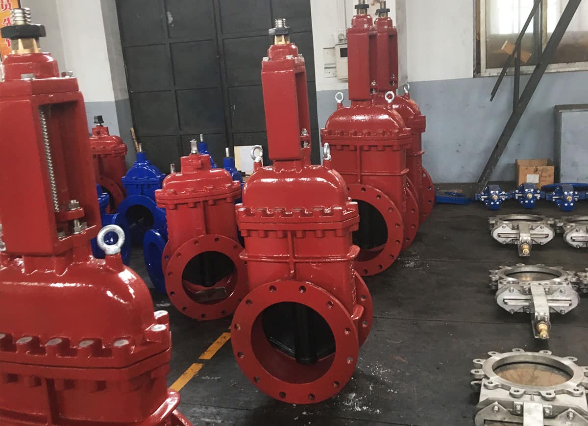
AWWA gate valve is mainly used in both municipal and fire-fighting systems. For gate valve used in fire-fighting system, it must have FM/UL certification. Judberd’s AWWA gate valve has passed the strict UL/FM test and thus obtained the UL/FM certificate, the following are the valve samples we used for testing.
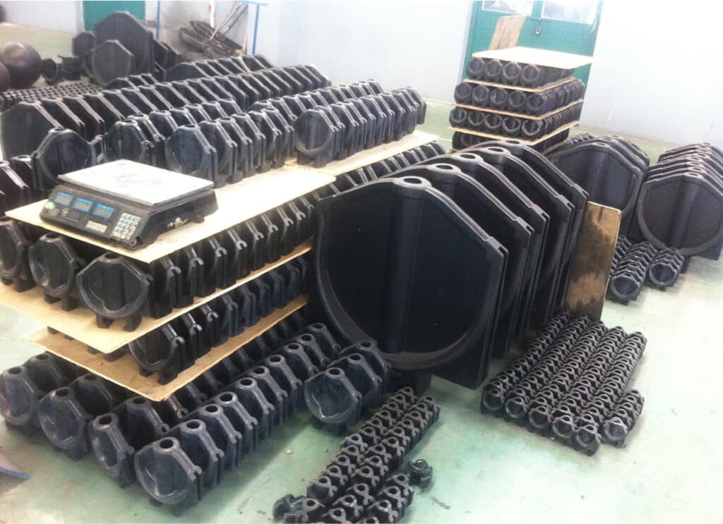
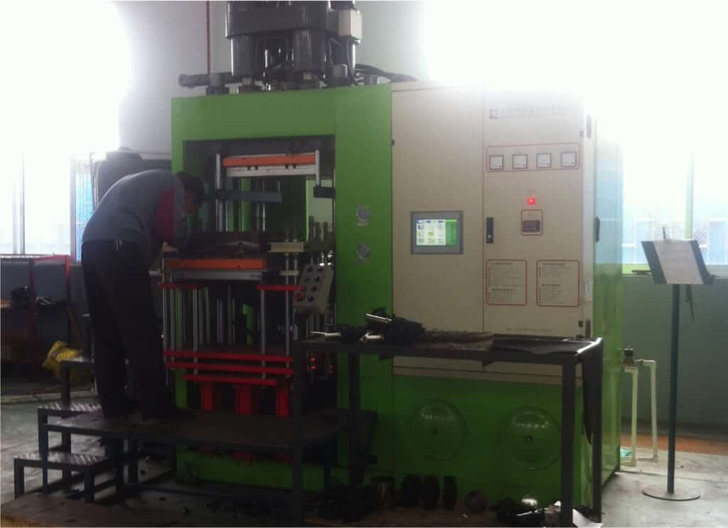
Producing process for EPDM
encapsulated gate valve wedge
The quality of the valve wedge is crucial to the whole valve, so to ensure the good quality of the valve, judberd wraps the valve wedge itself, which not only ensures the quality of the valve but also reduces the cost.
Application
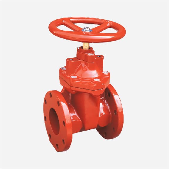
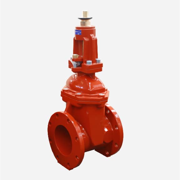
Flanged Connection _
Characteristics
The valve body and pipeline are connected with flanges using bolts.Provides a stable and strong connection, ideal for large diameter pipelines.Easy to install and remove, convenient for maintenance and replacement.
Application Scenarios
● Municipal water supply: Connects main water supply pipelines and branch lines.
● Industrial applications: Factories’ cooling water systems and process water systems that require high-strength connections.
● Sewage treatment: Large sewage treatment pipelines and facilities.
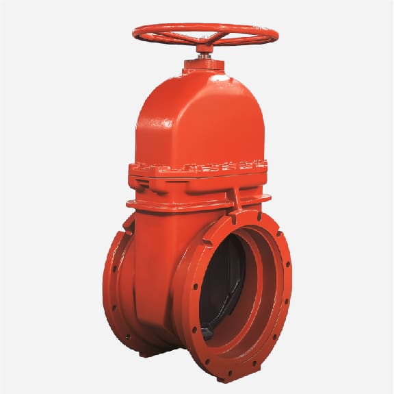
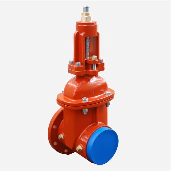
Mechanical Joint Connection _
Characteristics
Uses a rubber gasket and bolts and nuts to connect the valve and pipeline.Suitable for underground installations and can withstand some displacement and vibration.Easy to install, provides a strong connection, and is easy to maintain.
Application Scenarios
● Underground pipelines: Underground pipelines of municipal water supply and sewage treatment systems.
● Agricultural irrigation: Underground irrigation pipelines that require flexible connections.
● Fire systems: Underground fire water supply pipelines.
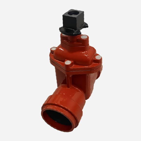
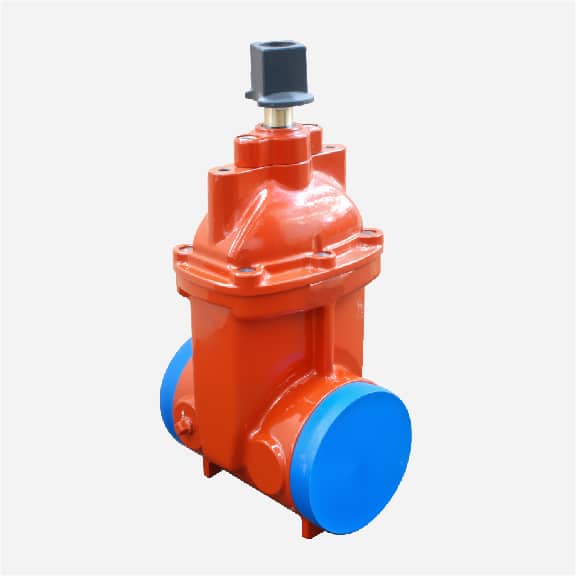
Socket Connection _
Characteristics
The pipe’s socket is inserted into the valve’s socket and sealed with a gasket.Provides a strong seal, suitable for systems with lower pressure.Ideal for connecting medium and small diameter pipelines, easy to install, and low cost.
Application Scenarios
● Residential water supply: Medium and small diameter water supply pipeline systems.
● Agricultural irrigation: Irrigation systems that require good sealing.
● Light industrial applications: Low-pressure process water pipelines.
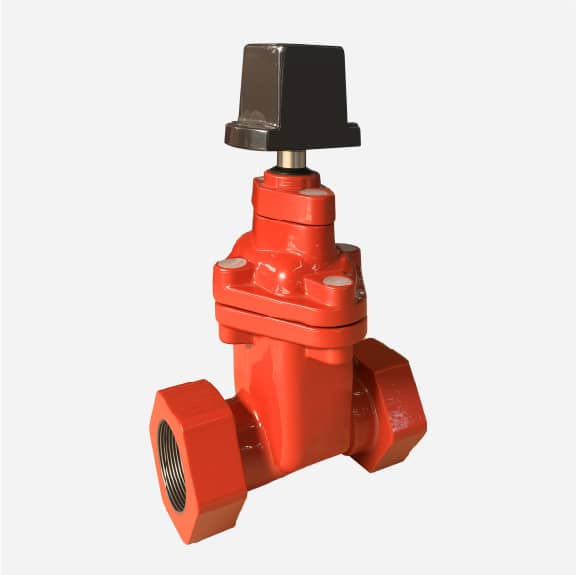
Threaded Connection _
Characteristics
The valve and pipeline are connected with threads, easy to assemble and disassemble.Ideal for connecting small diameter pipelines, quick to install.Reusable, suitable for systems that require frequent assembly and disassembly.
Application Scenarios
● Laboratories and small industrial applications: Small pipeline systems that require flexible connections.
● Residential water supply and irrigation: Small diameter water supply and irrigation pipelines.
● DIY projects: Home repairs and small projects.
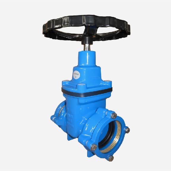
HDPE Pipe-Specific Restrained Joint _
Characteristics
Designed for HDPE pipes, the valve and HDPE pipe are connected using a special restrained joint device.Provides high strength and pull-out resistance, suitable for high-pressure and high-stress environments.Can withstand expansion and contraction of HDPE pipes, keeping the connection stable.
Application Scenarios
● High-pressure water supply systems: HDPE water supply pipelines that require high-strength connections.
● Mining and conveyance systems: Pipelines systems that convey slurry and high-pressure liquids.
● Gas transmission: Natural gas and industrial gas transmission pipelines.
Different connection methods are suitable for various application scenarios. Choosing the right connection method based on specific needs can ensure the safety, reliability, and long-term use of the system. Flanged connections are suitable for pipelines with large diameters and high-strength requirements; mechanical joints are suitable for underground and flexible systems; socket connections are suitable for medium and small diameter and low-pressure systems; threaded connections are suitable for small systems that require frequent assembly and disassembly; and HDPE pipe-specific restrained joints are suitable for high-pressure and high-stress HDPE pipe systems.
Installation
When installing an American Flow Control Gate Valve, you will need to follow different installation steps depending on the type of connection. Here are the detailed installation steps for the different types of connections:
Flanged Connection _
● Preparation Verify that the valve and pipe flanges are the same size and standard.
Check the flange gasket and bolt for completeness.
● Installation Steps Place the flange gasket between the valve and pipe flanges.
Align the bolt holes in the valve and pipe flanges.
Insert the bolts and hand tighten.
Using a torque wrench, tighten the bolts evenly and progressively in a diagonal sequence to ensure even pressure.
● Check Ensure all bolts are tightened to the recommended torque values.
Pressure test to verify no leaks.
Mechanical Joint (MJ) Connection _
● Preparation Verify the pipe outside diameter is the same size as the valve mechanical joint.
Have a gasket and mechanical joint accessory ready.
● Installation Steps Place the gasket over the pipe end.
Align the valve to the pipe end and ensure it is centered.
Connect the valve to the pipe using the mechanical joint accessory (nut, washer, etc.) hand tighten.
Using a torque wrench, tighten the mechanical joint accessory evenly and progressively in a diagonal sequence.
● Check Ensure all accessories are tightened to the recommended torque values.
Pressure test to verify no leaks.
Threaded Connection _
● Preparation Verify the valve and pipe thread type and size are the same.
Use the appropriate sealing material (such as Teflon tape or pipe dope).
● Installation Steps Evenly coat the threads on the valve or pipe with the sealing material.
Align the valve and pipe threads and hand tighten to start the connection.
Using the appropriate wrench, turn clockwise until tight.
● Check Ensure the threaded connection is secure and not loose.
Pressure test to verify no leaks.
Restrained Joint _
● Preparation Verify the pipe outside diameter is the same size as the valve Restrained Joint.
Have a gasket and Restrained Joint accessory ready.
● Installation Steps Place the gasket over the pipe end.
Align the valve to the pipe end and ensure it is centered.
Connect the valve to the pipe using the Restrained Joint accessory (clamp, bolt, etc.) hand tighten.
Using a torque wrench, tighten the Restrained Joint accessory evenly and progressively in a diagonal sequence.
● Check Ensure all accessories are tightened to the recommended torque values.
Pressure test to verify no leaks.
Post-Installation Notes
Clean _
Clean the installation site after installation to ensure no tools or debris are left behind.
Label _
Label the valve with the installation date and model number.
Maintain _
Regularly check the operation of the valve and perform necessary maintenance.
Ensure that all relevant safety regulations and operating procedures are followed during installation to ensure the safety of personnel and equipment.
American Flow Control Gate valve photos
Do You Need Quotation From Chinese Manufacturer?
Please Leave Us Your Information as Below,We will send you our Bottom Price As Soon As We Can
Do You Need Our Catalogue to Check More?
Please Leave Us Your Information as Below,We will send you our Professional Catalogue As Soon As We Can
Need a quotation?
I’m Here
To Assist You
Please leave your enquiry,We will reply you in 24 hours.