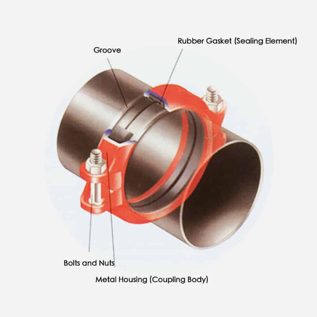
Grooved coupling is a fast-installation method that mechanically connects two pipes with grooved ends. The raised sections on the metal housing of the grooved coupling engage with the grooves on the pipe ends and are secured with bolts. Once you tighten the bolts, the housing clamps onto the grooves and compresses the gasket, which creates a mechanical lock (to keep the pipes from pulling apart) and a seal (to keep the medium from leaking).
Judberd is competitive manufacturer for many different types of groove couplings as below.If you need them, welcome you contact us.
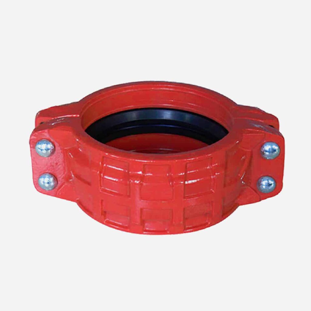
Ductile IronRigid Coupling
Series No. RGC001
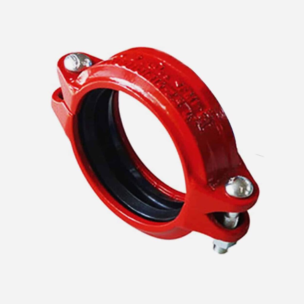
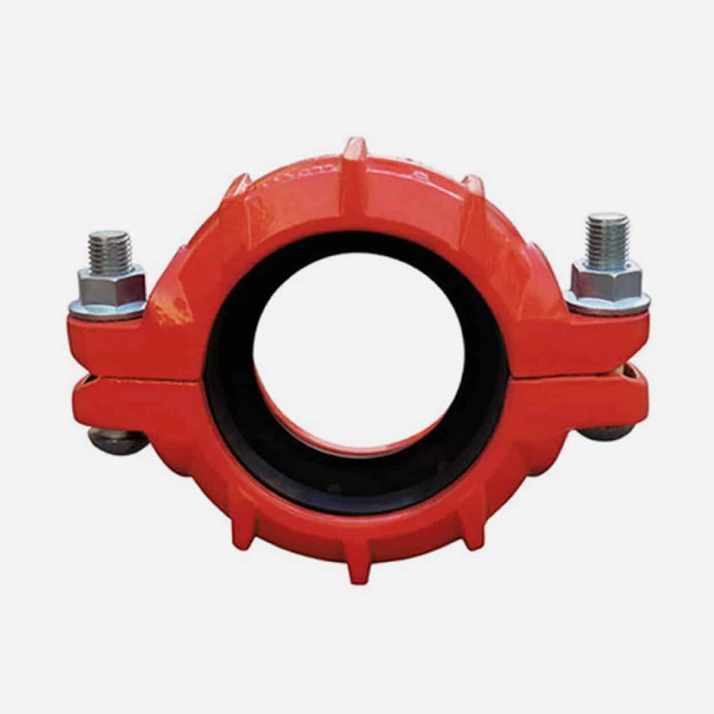
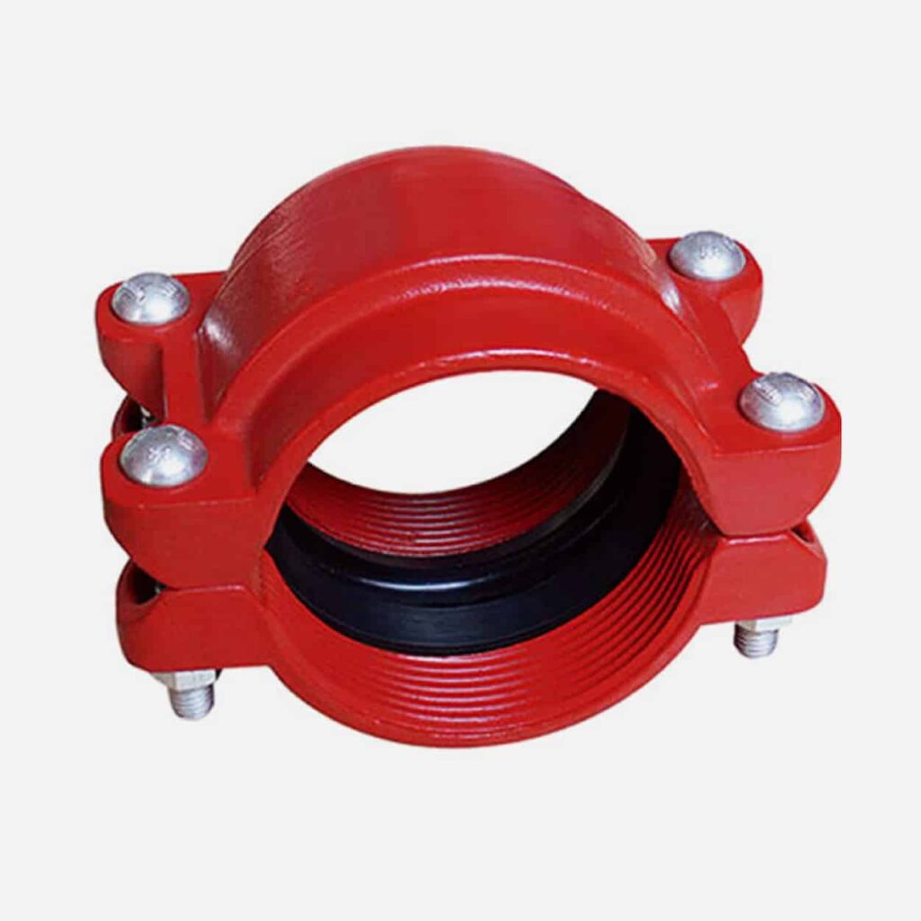
Ductile Iron Flexible Coupling(Working Pressure 5 Mpa for small size, 3 Mpa for big size)
Series No. FGC001
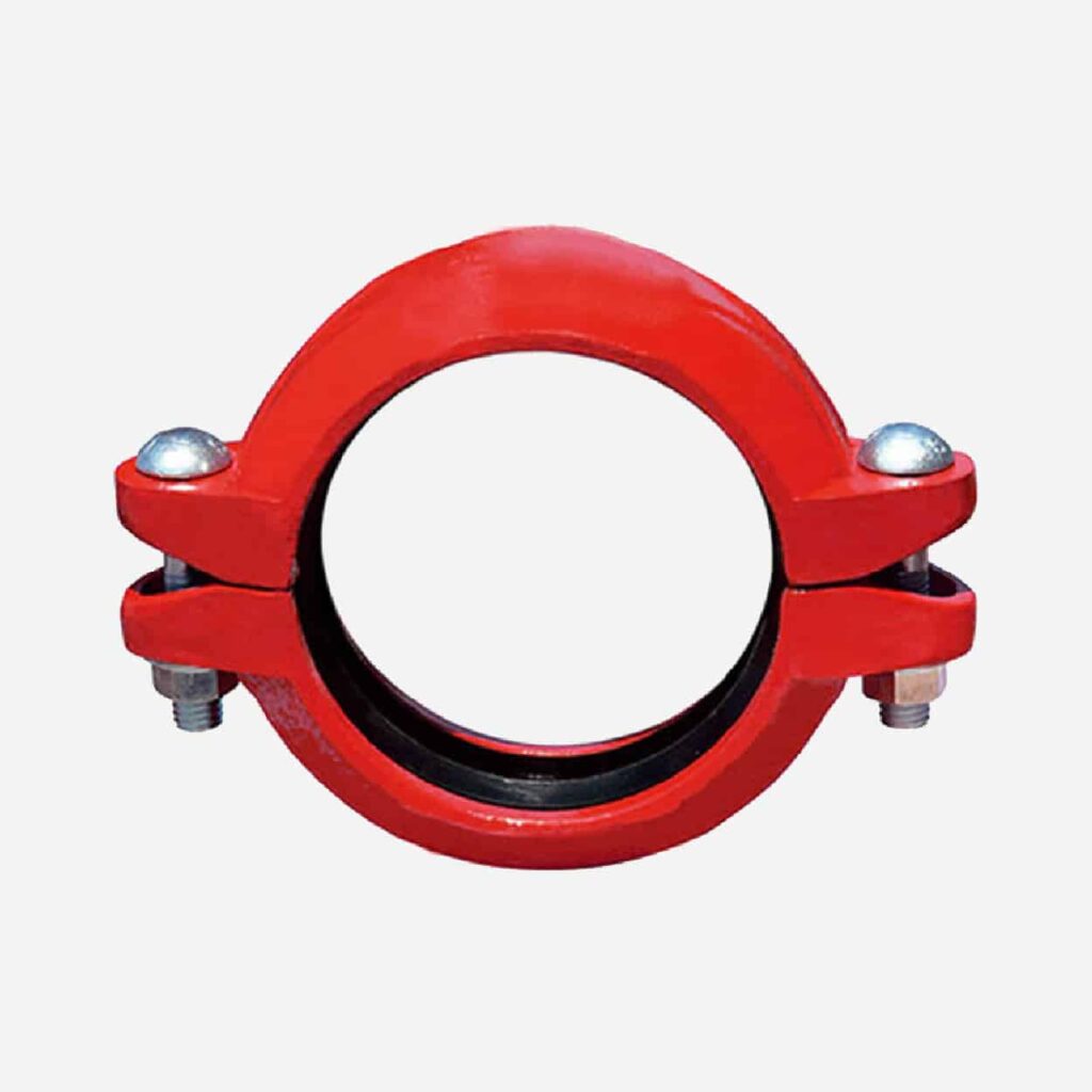
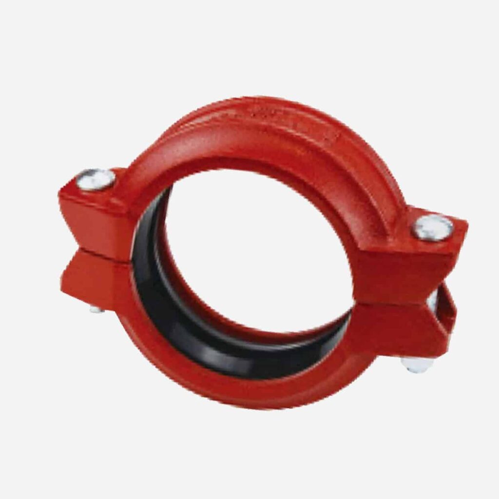
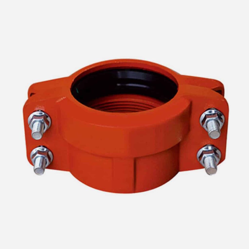
Ductile Iron Middle pressure flexible coupling(Working Pressure 7 Mpa for small size, 5 Mpa for big size)
Series No. FGC002
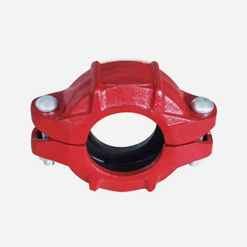
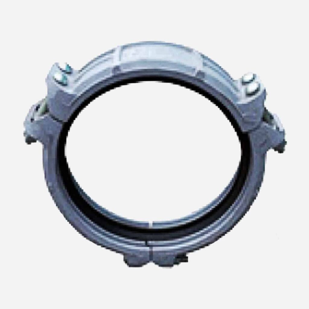
Ductile Iron High Pressure Flexible Coupling(Working Pressure 10 Mpa for small size, 8 Mpa for big size)
Series No. FGC002
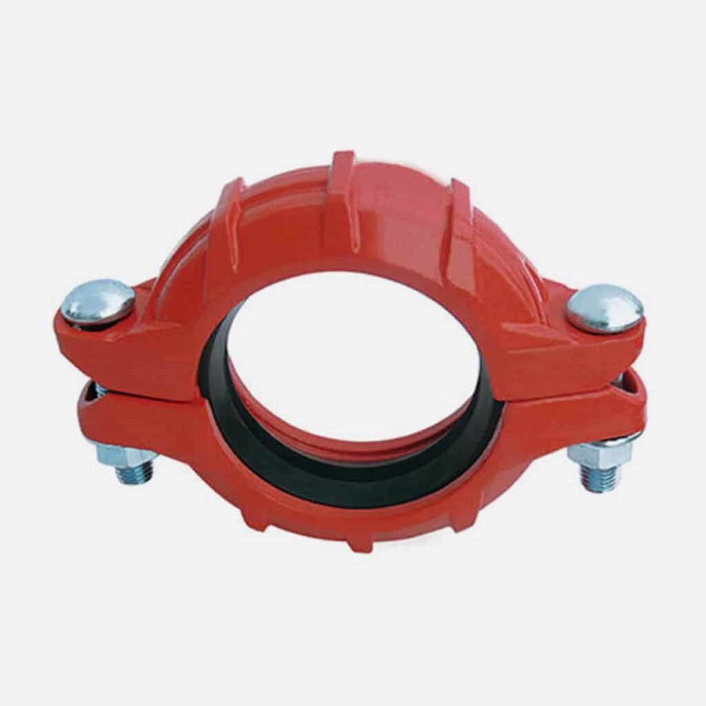
Ductile Iron Super high pressure flexible coupling(Working Pressure 15 Mpa for small size, 10.5 Mpa for big size)
Series No. FGC003
Ductile Iron Reducing Coupling
Series No. RGC001
Ductile Iron Shoulder Coupling which connects by relying on the raised shoulder at the end of the pipe
Series No. SGC001
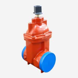
Ductile Iron Ring Joint Coupling
Series No. RJGC001
Ductile Iron Coupling for HDPE Pipe
Series No. GCFPE001
Ductile Iron Transition coupling for HDPE pipe to Steel pipe
Series No. TCPE-Steel001
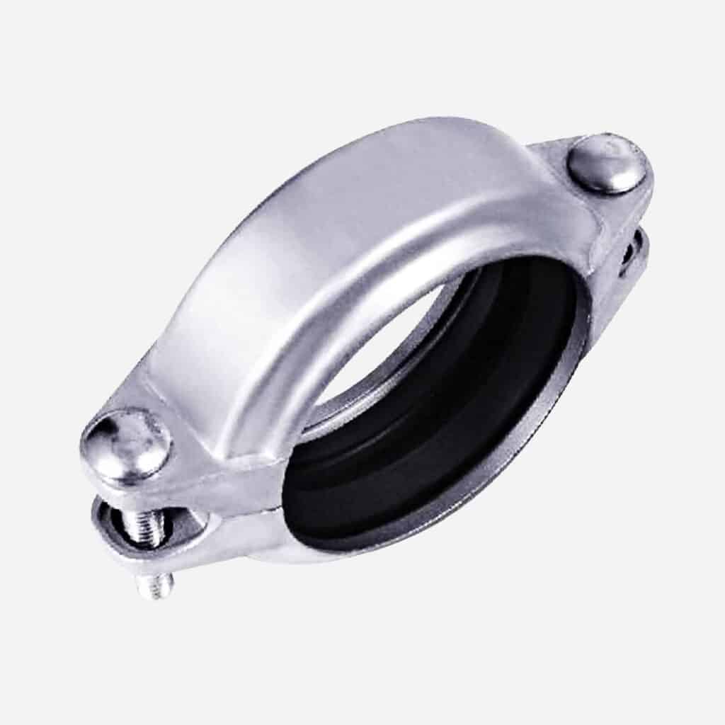
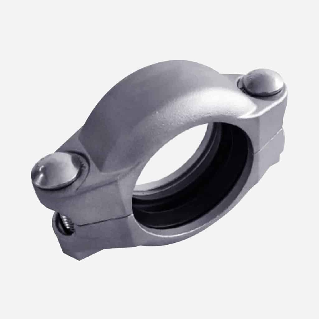
Stainless Steel Low-Pressure Flexible Groove Coupling with rated Working Pressure- 350 psi (25 bar)
Series No. SSFGC001
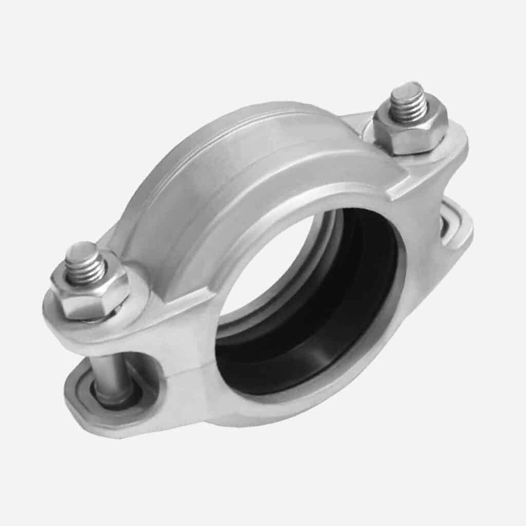
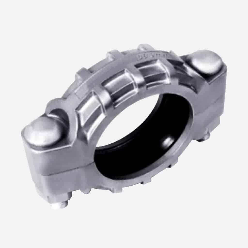
Stainless Steel Medium-Pressure Flexible Groove Coupling with Rated Working Pressure- 600 psi (42 bar)
Series No. SSFGC002
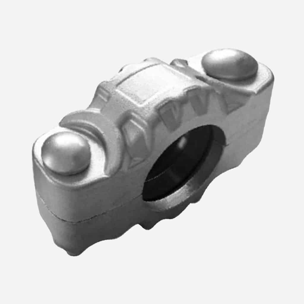
Stainless Steel High-Pressure Groove Flexible Coupling with rated Working Pressure- 1200 psi (83 bar)
Series No. SSFGC003
Stainless Steel High-Pressure Groove Flexible Coupling with rated Working Pressure- 1500 psi (100 bar)
Series No. SSFGC004
Stainless steel ultra high-pressure flexible groove coupling with rated working pressure- 2320 psi (160 bar)
Series No. SSFGC005
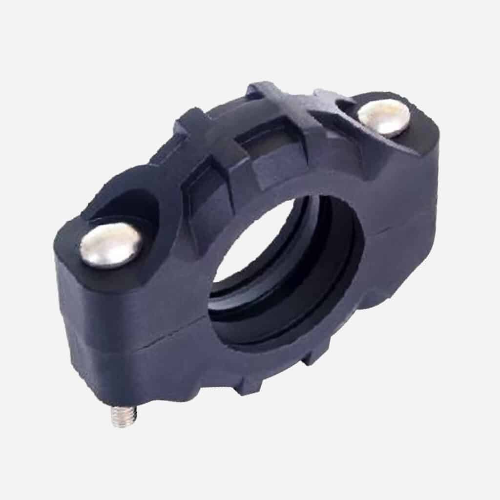
Corrosion-resistant flexible groove coupling with maximum working pressure is 300 psi (21 bar)
Series No. SSFGC006
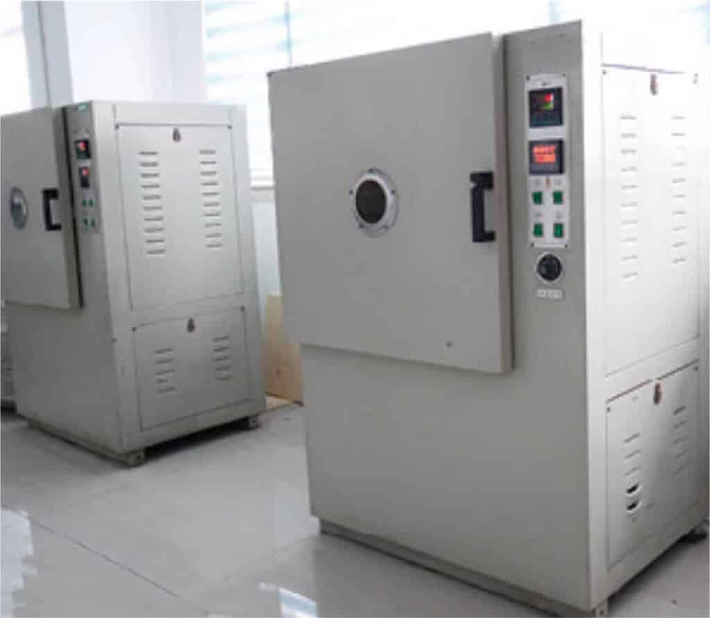
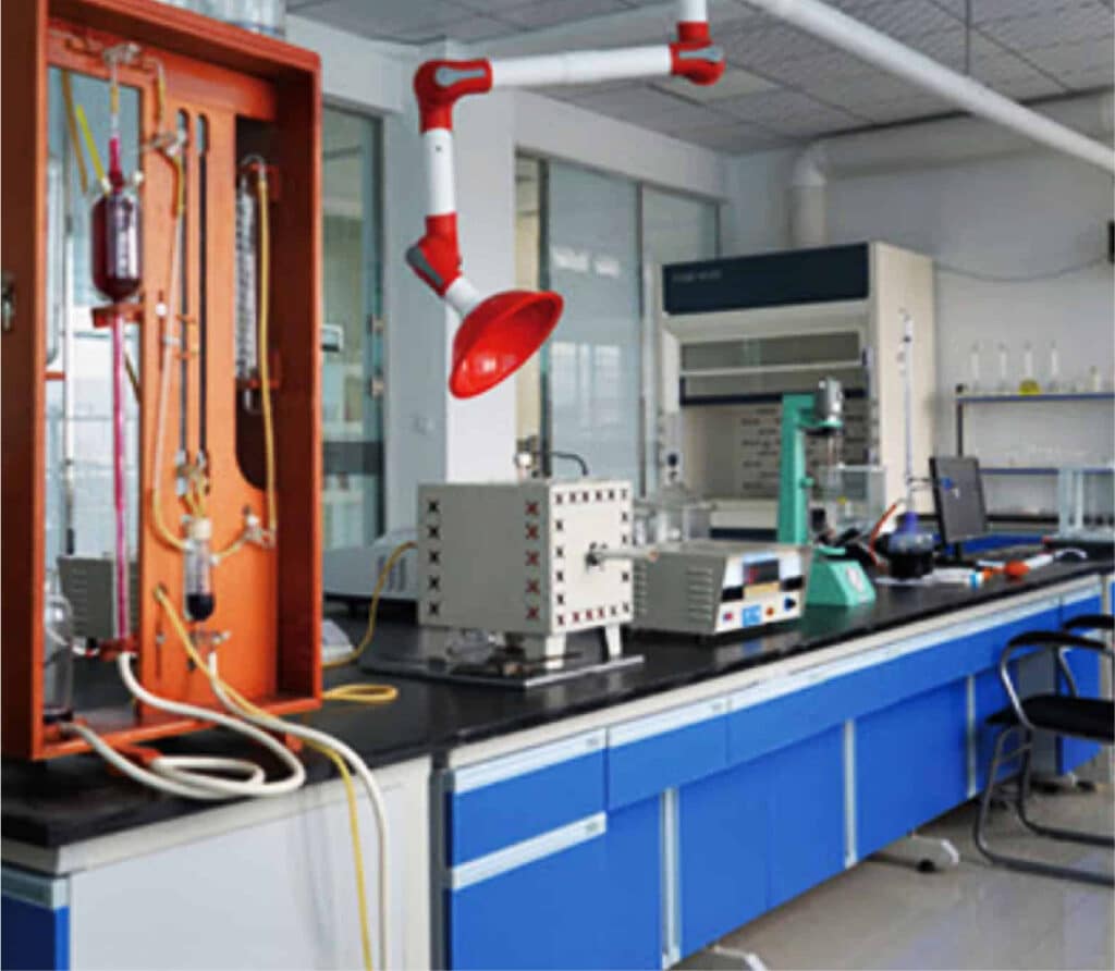
Tests for Grooved Couplings
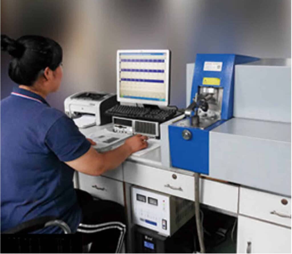
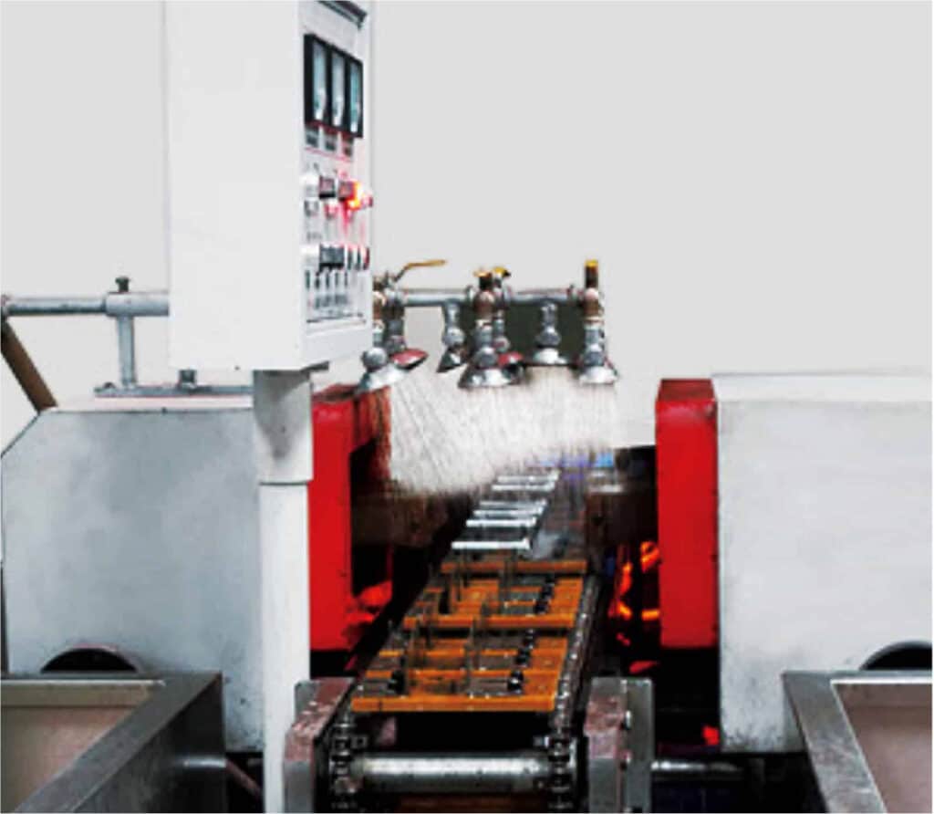
Judberd uses a Danish DISA vertical molding production line, which ensures high precision and stable product dimensions. The foundry is equipped with a U.S.-made INDUCTOTHERM medium-frequency furnace and automatic pouring machines, effectively preventing the entry of harmful impurities and ensuring uniform molten iron composition. The composition is tested and adjusted using a direct-reading spectrometer and molten iron quality management instruments.
A digital molten iron thermometer controls the temperature to ensure every batch meets required standards.
Our chemical laboratory is equipped with advanced testing instruments, including a rapid direct-reading spectrometer, molten iron management device, carbon-sulfur analyzer, and UV-visible spectrophotometer.
We perform fast and accurate chemical analysis of raw materials and also conduct real-time composition control during the production process. This ensures that every step of the manufacturing process meets specifications and that each finished product complies with quality requirements from the chemical composition level.
Below is our mill test for your reference.
Spectrometer testing
Chemical composition analysis
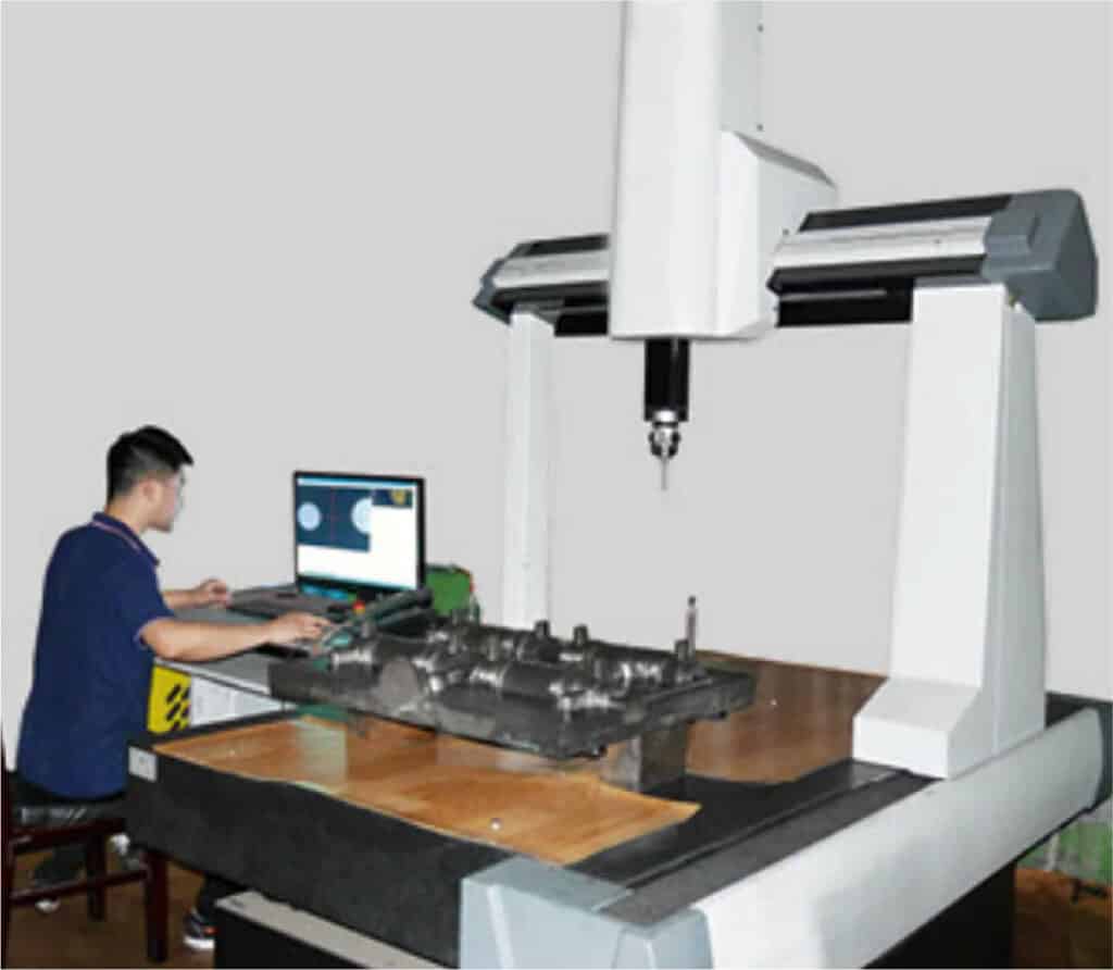
Coordinate Measuring Machine (CMM)
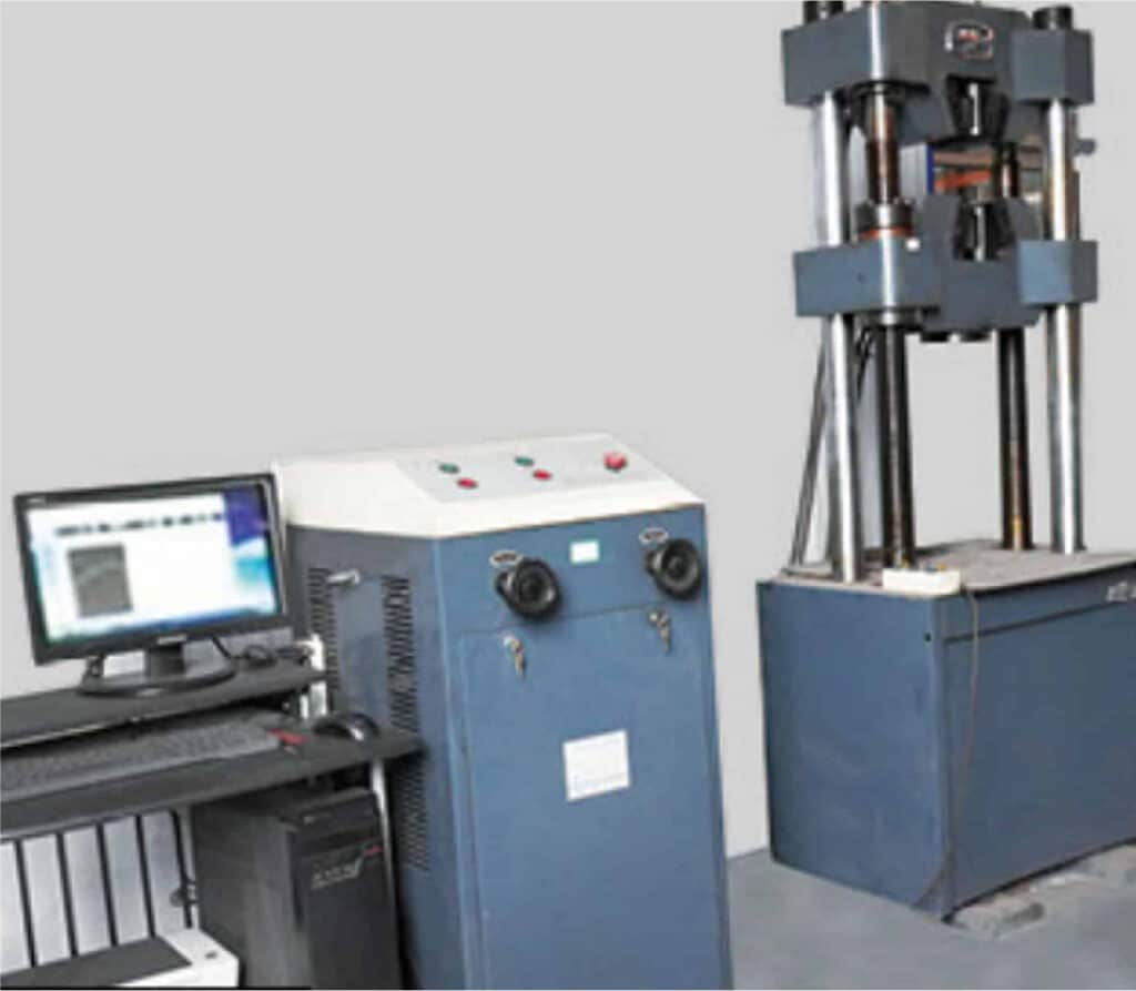
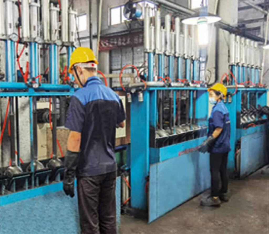
Bolt tensile strength testing
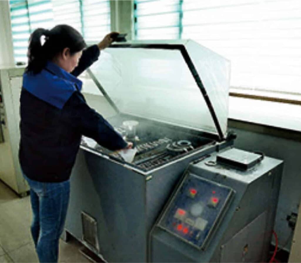
Magnetic particle inspection
Rubber gasket tensile test
Back to all pipe couplings
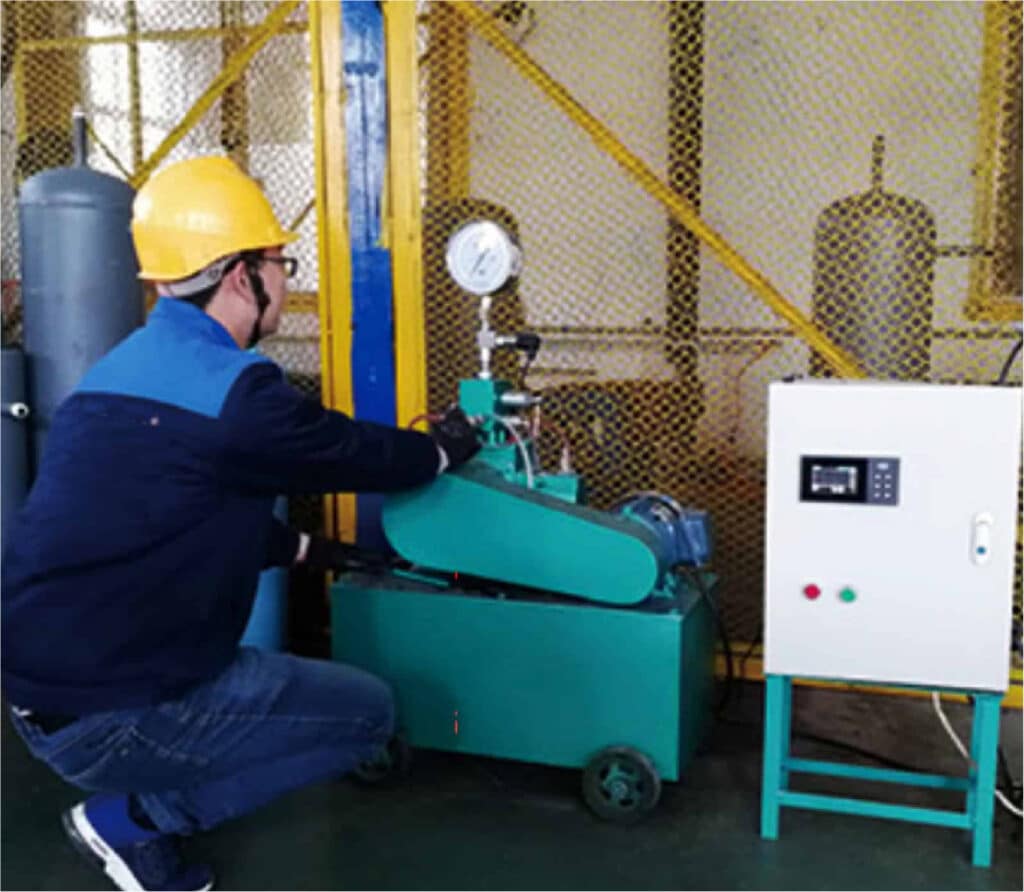
Electric Pressure Testing Pump
Pressure testing
Carbon-sulfur analyzer
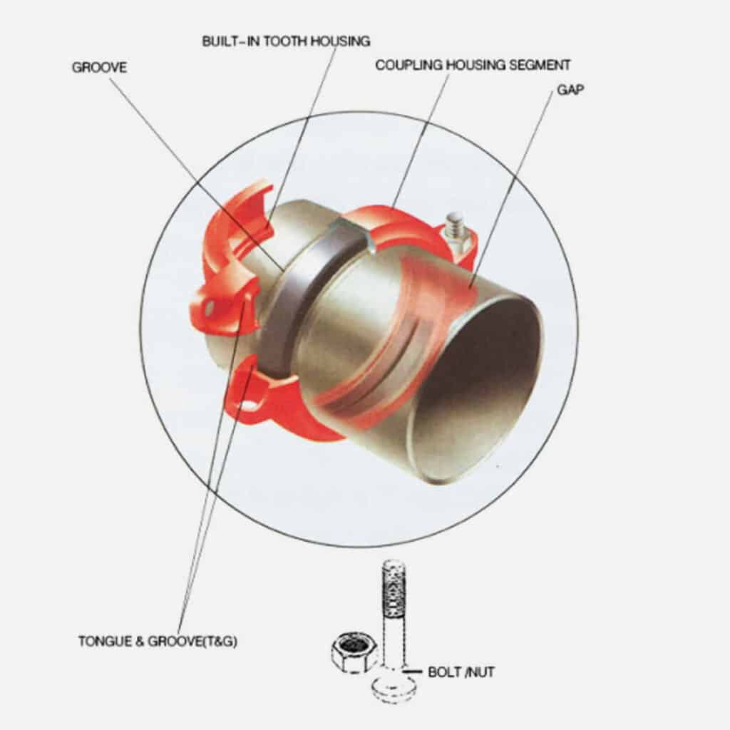
Grooved Coupling Structure
Grooved coupling consists of three main parts:
● Metal Housing (Coupling Body) Usually a two-piece design made from ductile iron or carbon steel.Has raised sections on the inside that engage with the grooves on the pipe ends to create a mechanical lock.
● Rubber Gasket (Sealing Element) Placed between the pipe ends to create a leak-proof seal.Common materials: EPDM (for water), NBR (for oil), FKM (for high-temperature or corrosive media).
Bolts and Nuts Used to tighten the coupling housing and compress the gasket to ensure a secure and sealed connection.
How Grooved Coupling Works
01
The pipe ends are machined or rolled to create standard grooves.
02
A rubber gasket is placed over one pipe end.
03
The second pipe is inserted to meet the first.
04
The metal coupling housing is placed around the gasket and aligned with the pipe grooves.
05
Bolts are tightened:The housing grips the grooves, locking the pipes together.The gasket is compressed, forming a tight seal to prevent leakage.
There are two main types:Rigid Coupling – Fixed connection with no movement.Flexible Coupling – Allows limited axial movement or angular deflection, ideal for vibration or thermal expansion.
Grooved Coupling Types and Their Difference
Grooved couplings are mainly divided into two types: Rigid Coupling and Flexible Coupling.Their difference is as below
Feature
Rigid Coupling
Flexible Coupling
Movement
No movement allowed after installation
Allows slight axial and angular movement
Purpose
Creates a strong, fixed connection
Absorbs vibration, thermal expansion, and misalignment
Typical Use
Main pipelines, pump rooms
Firefighting systems, HVAC, underground pipelines
Pressure Tolerance
Generally higher
Slightly lower but better flexibility
Installation Tolerance
Requires precise alignment
Easier, with more installation flexibility
Rigid Couplings are used for below situation _
1, When the pipe system must remain fixed and cannot move
2, For main pipelines or straight sections that need solid support
3, To replace welding or flange connections with a strong mechanical joint
Flexible Coupling are used for below situation _
1, When there’s vibration, thermal expansion, or slight misalignment
2, In long pipelines that may expand or shift
3, For fire protection, air conditioning water systems, or buried pipes
Most systems use both types.Use Rigid Coupling on main lines for strength.Use Flexible Coupling on branch lines or areas that need flexibility.
Selection Guide
Groove couplings come in different types, such as Rigid Coupling, Flexible Coupling, and Shoulder Coupling, and each is designed for specific piping conditions. Choosing the correct type is essential for ensuring safety, reliability, and ease of installation. Below is a detailed guide on when to use each type, based on common applications like fire protection systems, HVAC, and industrial pipelines.
Rigid Coupling _
● Function Creates a firm, immovable connection between pipes, Prevents axial and angular movement, Ensures high stability and alignment
● Recommended For Fire protection mains (vertical risers, horizontal headers), Pipes fixed with hangers or supports, Areas where no pipe expansion or vibration is expected
Flexible Coupling _
● Function Allows controlled axial, angular, and radial movement, Absorbs vibration and accommodates thermal expansion, Easier to install on slightly misaligned pipes
● Recommended For Branch lines in fire protection systems, HVAC pipelines (chilled/hot water systems), Pump connections or long pipeline runs with thermal expansion, Slight pipe misalignment or areas with movement
Shoulder Coupling _
● Function Designed for pipes that cannot be grooved, Uses a mechanical “shoulder” profile to secure the pipe, No need to roll or machine grooves
● Recommended For Thin-wall stainless steel pipes, Large-diameter pipes that are difficult or unsafe to groove, Lined or coated pipes (e.g. epoxy, plastic-lined), Underground or municipal pipelines, Pre-fabricated piping systems
Typical Application Scenarios
Fire Protection Systems _
● Main Pipes Use Rigid Coupling to keep connections stable and fixed
● Branch Pipes Use Flexible Coupling to allow for movement and expansion
● Thin-wall/Pre-coated Pipes Use Shoulder Coupling to avoid damaging the pipe with grooves
HVAC Systems _
● Temperature-sensitive pipelines: Use Flexible Coupling to absorb thermal changes
● Wall penetrations or fixed points: Use Rigid Coupling
● Large-diameter or coated pipes: Use Shoulder Coupling
Industrial Pipelines _
● Vibration-prone areas (e.g., near pumps): Use Flexible Coupling
● Fixed installations with no movement: Use Rigid Coupling
● Pipes that can’t be grooved (lined or fragile materials): Use Shoulder Coupling
To help you select the right groove coupling, please confirm Pipe material and wall thickness, Pipe diameter, Installation location (indoor, outdoor, underground), Expected movement, temperature changes, or vibration, Whether grooving is possible or not, Certification requirements (e.g. UL/FM for fire protection systems)
If you’re unsure which type fits your project, feel free to contact Judberd. Our team will provide tailored advice and reliable solutions based on your actual pipeline conditions.
Make sure both pipes have proper grooves (according to AWWA C606 or ISO standards), No dents or cracks near the groove area, Clean pipe ends—remove oil, rust, dust, or burrs.
Use a cloth to wipe the grooves clean. The better the contact, the better the seal!
Step 2, Check the Gasket _
Select the right gasket material (EPDM for water, NBR for oil, etc.), Inspect the gasket for any damage or dirt.
Apply a thin layer of lubricant on the inside of the gasket. This helps with sealing and makes it easier to slide on.
Never use grease or oil-based lubricant unless approved.
Step 3, Install the Gasket _
Stretch the gasket slightly and place it evenly over one pipe end, half covering the groove.Bring the second pipe close and align the ends so the gasket can cover both grooves equally.
Make sure pipes are aligned properly—no gaps or angles.
Step 4, Install the Coupling Housing _
Place both coupling halves over the gasket, ensuring they sit in the grooves on both pipes.Insert the bolts through the housing holes.
Tip: Start by hand-tightening the nuts evenly.
Step 5, Tighten the Bolts _
Use a socket wrench to tighten the bolts alternately (like tightening car wheels), so pressure is even on both sides.Tighten until the housing halves come together, with metal-to-metal contact (no gap).If using a torque wrench, follow the manufacturer’s torque values.
Step 6, Final Inspection _
Check alignment: the coupling should be centered, and the pipes should be straight.Check tightness: no visible gasket, bolts are secure.Turn on water or air pressure slowly to test for leaks.
Notes
1, Do not over-tighten; it can damage the gasket.
2, Do not use damaged gaskets or housings.
3, If there is vibration or movement in the system, consider using flexible couplings.
4, If you follow these steps carefully, a non-professional can install grooved couplings successfully. However, for large-diameter pipes, high-pressure systems, or critical projects, it’s better to have installation reviewed or guided by someone experienced.
5, Measure twice, align carefully, and tighten evenly.
Standards & Certifications
Standard
Name
Description
AWWA C606
American Water Works Association
Design, dimensions, and performance requirements for grooved joints
ANSI / ASME B31.1 / B31.3
American Society of Mechanical Engineers
Pipeline system standards for industrial and power applications
UL Listed
Underwriters Laboratories
Fire protection safety certification (commonly used in sprinkler systems)
FM Approved
Factory Mutual
Fire protection certification for high pressure, vibration, and durability
ISO 6182
International Organization for Standardization
Fire protection systems and components
EN 10242 / EN 1092
European Norms
Standard for European mechanical and piping systems