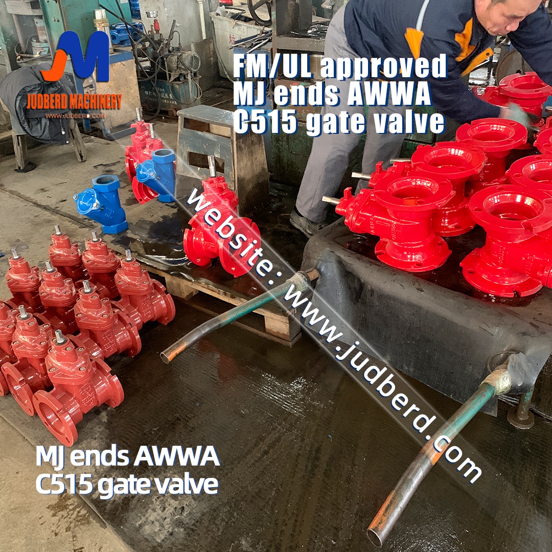
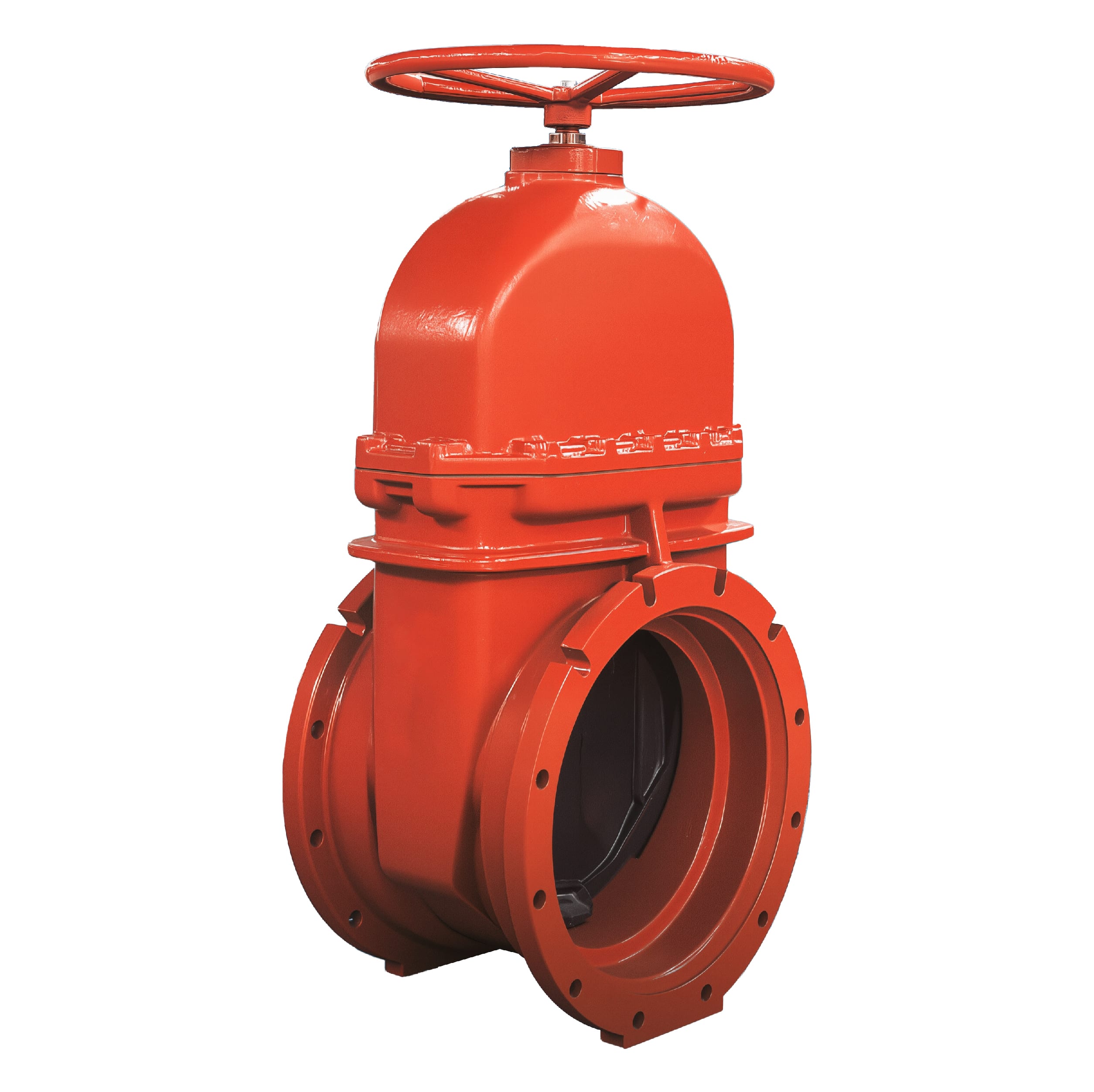
AWWA C515 NRS Resilient Seated Gate Valve, Mechanical Joint Ends
Mechanical joint gate valve is a type of gate valve designed with a mechanical joint connection for attaching to pipes. This connection method is commonly used in water supply and wastewater systems.
Specification
● Design Standard AWWA C515
● Non-Rising Stem, Resilient Seated
● Face to Face: ASME B16.10.
● MJ*MJ to AWWA C111/A21.11-12
(FL*MJ available upon request)
● Inspection & testing: AWWA C515
● Fusion Bonded Epoxy Coated Interior and Exterior to AWWA C550 Standard
Use
● Working Pressure:250PSI
(200 and 300 PSI available on request)
● Working Temperature:-20℃ to 100℃(-4°F to 212°F)
● Operator:Handwheel,2”Operating Nut,Gearbox
● UL/FM approved
Drawing
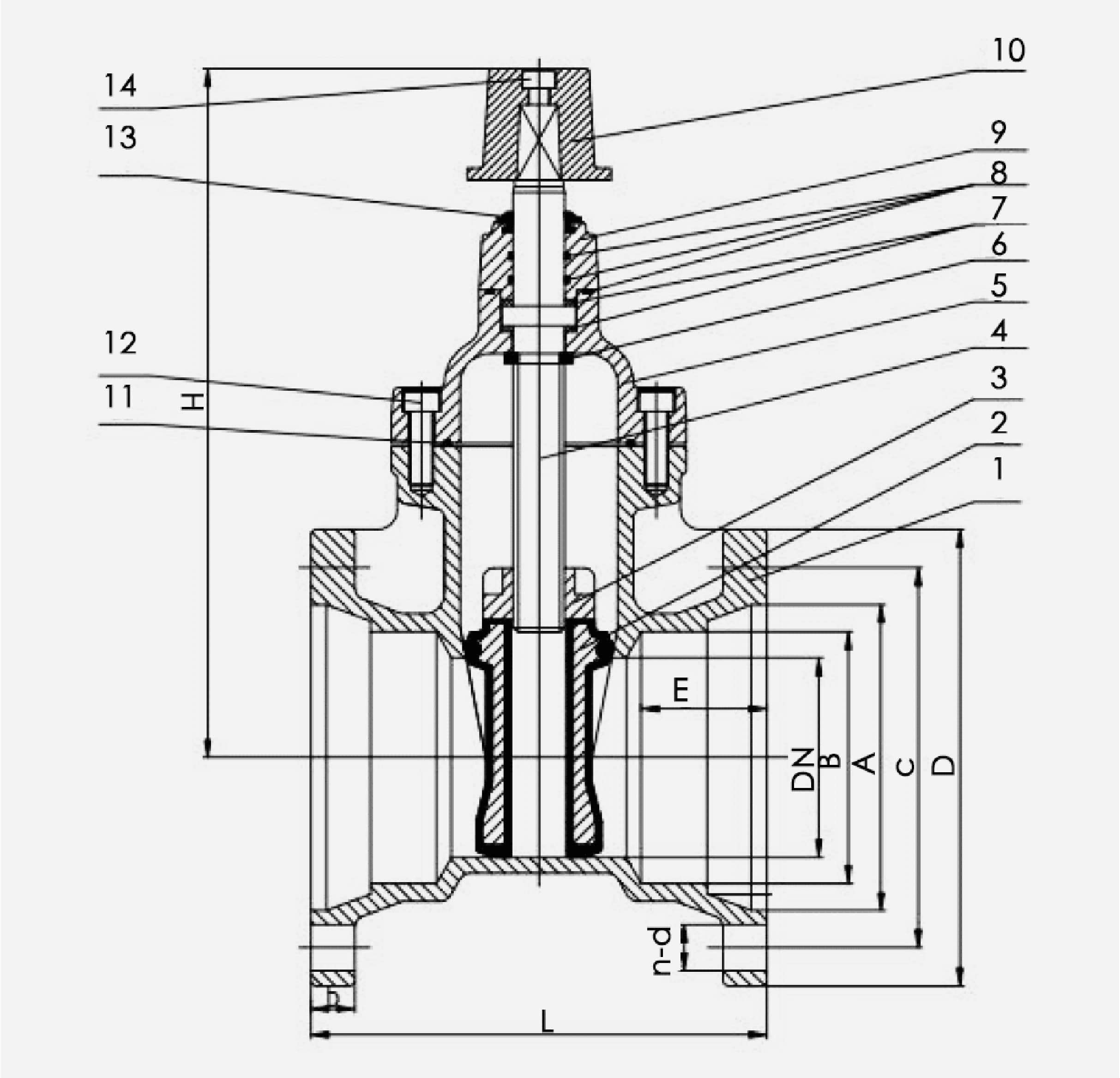
Material specification
| No | Part | Material |
|---|---|---|
| 1 | Body | Ductile lron ASTM A536 |
| 2 | Wedge | Ductile lron EPDM/NBR Encapsulated |
| 3 | Wedge Nut | Brass ASTM B124 C37700 |
| 4 | Stem | Stainless Steel AISI 420 |
| 5 | Bonnet | Ductile lron ASTM A536 |
| 6 | Wedge Nut Gasket | Rubber NBR |
| 7 | Washers | Nylon/Brass ASTM B124 C37700 |
| 8 | O-ring | Rubber NBR |
| 9 | Gland | Ductile lron ASTM A536 |
| 10 | Operating Nut | Ductile lron ASTM A536 |
| 11 | Bonnet Gasket | Rubber NBR |
| 12 | Bonnet/Gland Bolt | CS With ZINC Plated/SS304 |
| 13 | Dust Cap | Rubber NBR |
| 14 | Top Bolts | CS With ZINC Plated/SS304 |
DIMENSIONS AWWA C111/A21.11-12 C515-09(b)
| inch | L | H | C | D | b | n-d | A | E | B | |||||||||
|---|---|---|---|---|---|---|---|---|---|---|---|---|---|---|---|---|---|---|
| mm | inch | mm | inch | mm | inch | mm | inch | mm | inch | mm | inch | mm | inch | mm | inch | mm | inch | |
| 2" | 210 | 8.27 | 262 | 10.31 | 120.5 | 4.74 | 157.2 | 6.19 | 16 | 0.63 | 2-19 | 2-0.75 | 90 | 3.54 | 63.5 | 2.5 | 67.5 | 2.66 |
| 3" | 203 | 7.99 | 283 | 11.14 | 157.2 | 6.19 | 195 | 7.68 | 19.1 | 0.75 | 4-19 | 4-0.75 | 125.5 | 4.94 | 63.5 | 2.5 | 103.5 | 4.07 |
| 4" | 229 | 9.02 | 351 | 13.8 | 190.5 | 7.5 | 231 | 9.09 | 19.1 | 0.75 | 4-22.3 | 4-0.88 | 153 | 6.02 | 63.5 | 2.5 | 124.5 | 4.9 |
| 6" | 267 | 10.51 | 453 | 17.83 | 241.3 | 9.5 | 282 | 11.1 | 19.1 | 0.75 | 6-22.3 | 6-0.88 | 206.5 | 8.13 | 63.5 | 2.5 | 178 | 7.01 |
| 8" | 292 | 11.50 | 559 | 22.01 | 298.5 | 11.75 | 340 | 13.39 | 22.2 | 0.87 | 6-22.3 | 6-0.88 | 261 | 10.28 | 63.5 | 2.5 | 232.5 | 9.15 |
| 10" | 330 | 12.99 | 668 | 26.3 | 355.6 | 14 | 397 | 15.63 | 23.8 | 0.94 | 8-22.3 | 8-0.88 | 313.5 | 12.34 | 63.5 | 2.5 | 284.5 | 11.2 |
| 12" | 356 | 14.02 | 753 | 29.65 | 413 | 16.26 | 454 | 17.87 | 25.4 | 1.00 | 8-22.3 | 8-0.88 | 367 | 14.45 | 63.5 | 2.5 | 338 | 13.31 |
| 14" | 381 | 15.00 | 918 | 36.14 | 476.3 | 18.75 | 523 | 20.59 | 25.4 | 1.00 | 10-22.3 | 10-0.88 | 420.5 | 16.56 | 88.9 | 3.5 | 392.5 | 15.45 |
| 16" | 406 | 15.98 | 975 | 38.39 | 533.4 | 21 | 580 | 22.83 | 25.4 | 1.00 | 12-22.3 | 12-0.88 | 474 | 18.66 | 88.9 | 3.5 | 445.7 | 17.55 |
| 18" | 432 | 17.01 | 1067 | 42.01 | 590.6 | 23.25 | 638 | 25.12 | 25.4 | 1.00 | 12-22.3 | 12-0.88 | 527 | 20.75 | 88.9 | 3.5 | 499 | 19.65 |
| 20" | 457 | 17.99 | 1199 | 47.20 | 647.7 | 25.5 | 695 | 27.36 | 28.6 | 1.13 | 14-22.3 | 14-0.88 | 580.5 | 22.85 | 88.9 | 3.5 | 552.5 | 21.75 |
| 24" | 508 | 20.00 | 1363 | 53.66 | 762 | 30 | 810 | 31.89 | 30.1 | 1.19 | 16-22.3 | 16-0.88 | 687 | 27.05 | 88.9 | 3.5 | 659 | 25.94 |
Installation
Mechanical joint is a method used to connect pipes and valves, and its main working principle is to
create a strong and sealed connection by compressing the rubber sealing ring and using bolt fasteners.
Here are detailed descriptions of its working principle and installation steps:
Working Principle
Compression of the Sealing Ring
_
In a mechanical joint, a rubber sealing ring is placed between the pipe and valve contact surfaces. By tightening the bolts, the sealing ring is compressed to form a tight seal, preventing fluid leakage.
Bolt Fastening
_
Mechanical joints typically feature a set of bolts and nuts, and by evenly tightening these bolts, the connection is secured and sealed. The bolt tightening force secures the pipe and valve in place while compressing the sealing ring.
Installation Steps
Preparation
_
Inspect the end faces of the pipe and valve to ensure they are clean and free of debris.
Have all necessary components ready, including the valve, rubber sealing ring, bolts, nuts, and washers.
Install the Sealing Ring
_
Place the rubber sealing ring over the end of the pipe, ensuring it is positioned correctly.
Align the Pipe and Valve
_
Align the valve with the end of the pipe, ensuring the centerlines of the valve and pipe are aligned.
Insert the Bolts
_
Insert the bolts into the connecting holes on the valve and pipe, ensuring the bolts pass through the entire connection.
Install the Nuts and Washers
_
Place the washers and nuts on the bolts, preparing for tightening.
Evenly Tighten the Bolts
_
Using a wrench or another suitable tool, gradually and evenly tighten all the bolts. Ensure each bolt receives even tightening to avoid bias pressure and ensure the sealing ring is evenly compressed.
It is recommended to tighten the bolts in a cross-diagonal pattern to ensure even pressure distribution.
Check the Seal
_
After the bolts are tightened, conduct a leak test to ensure there are no leaks at the connection.
If leaks are found, you may need to further tighten the bolts or check the installation of the sealing ring.
Installation Notes
Proper Alignment
_
Ensure the pipe and valve are aligned during installation to avoid deviations that could affect the sealing effect.
Even Tightening
_
When tightening the bolts, apply force evenly to prevent seal failure due to uneven force.
Regular Inspection
_
After installation, regularly check the tightening status of the bolts and the condition of the sealing ring to prevent loosening and leaking due to vibration or other reasons.
By following the above steps and notes, you can ensure the reliability and sealing of mechanical joints,
making them suitable for various water supply, drainage, and industrial piping systems.
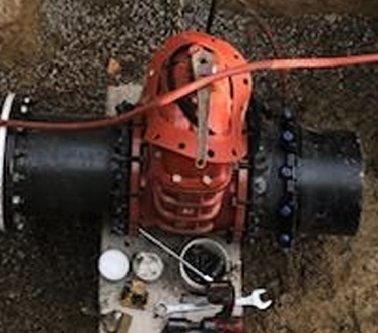
Application
AWWA mechanical joint gate valves are widely used in water supply and drainage systems, featuring reliable sealing performance and a straightforward installation process.
Here are the main applications and reasons for using them:
Applications
Municipal Water Supply Systems
● Reason:
AWWA mechanical joint gate valves are widely used in municipal water supply networks to control and isolate water flow. Their reliable sealing performance and durability ensure long-term leak-free operation, making them suitable for use on mains and branch pipelines.
Sewage Treatment Systems
● Reason:
They are used in sewage treatment systems due to their corrosion-resistant materials and robust construction that allows them to be used in sewage environments for extended periods. Mechanical joints are flexible and maintain their seal during pipe expansion and contraction and ground settlement.
Fire Protection Systems
● Reason:
In fire pipeline systems, AWWA mechanical joint gate valves open and close quickly, providing reliable water control. Additionally, the mechanical joint is easy to maintain and replace, ensuring the reliability of the fire protection system.
Industrial Piping Systems
● Reason:
Industrial piping systems (such as petrochemicals, pharmaceuticals, food and beverages) require valves that are resistant to high temperatures and pressures. The design of AWWA mechanical joint gate valves allows them to be used to transport and control a variety of industrial fluids.
Agricultural Irrigation Systems
● Reason:
In agricultural irrigation systems, these valves are used to control the flow and direction of irrigation water. Their robust and durable design is suitable for outdoor use, and the mechanical joint makes them easy to install and maintain.
Analysis of Reasons
EXCELLENT SEALING PERFORMANCE
AWWA mechanical joint gate valves use rubber sealing rings that create a tight seal through the mechanical joint, preventing fluid leaks and ensuring the efficient operation of the system.
SIMPLE INSTALLATION
Mechanical joints are simpler and faster than welding or flanged connections, making them suitable for on-site installation and emergency repairs. The bolt and sealing ring design allows them to be used flexibly under different pipeline conditions.
STRONG ADAPTABILITY
Mechanical joint gate valves can adapt to slight pipe misalignment and geological changes, providing greater installation and operational flexibility. The elastic design of the mechanical joint effectively prevents leaks and damage due to pipe expansion and contraction and ground settlement.
HIGH DURABILITY
These valves are typically made from corrosion-resistant materials, allowing them to be used long-term in harsh environments, reducing maintenance and replacement frequency, and lowering operating costs.
VERSATILITY
Designed and built for various types of fluids and operating conditions, AWWA mechanical joint gate valves are widely used in water supply, sewage treatment, industrial, and agricultural applications, demonstrating their versatility and efficiency.
In summary, AWWA mechanical joint gate valves are indispensable control devices in various pipeline systems due to their excellent sealing performance, straightforward installation process, strong adaptability, and high durability.
