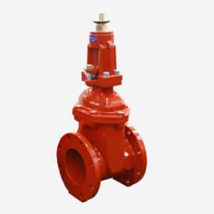
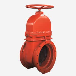
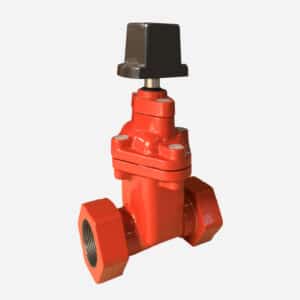
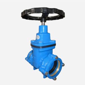
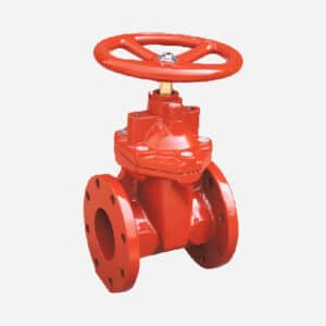
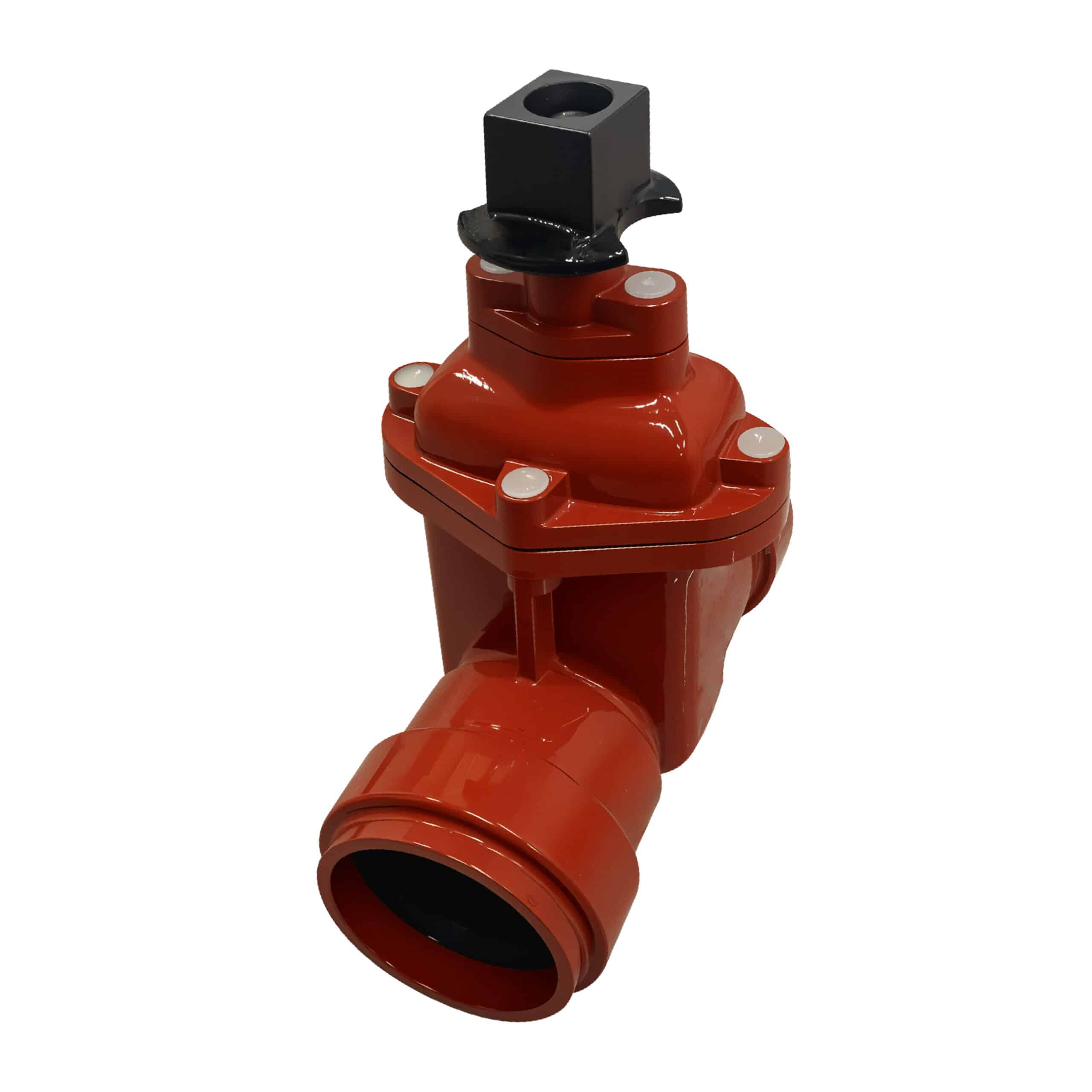
AWWA C515 NRS Resilient Seated Gate Valve , Push Fit Ends
Push fit gate valve is a type of valve that uses a push-fit mechanism to connect to pipes, allowing for a quick and easy installation without the need for traditional threading, welding, or soldering.
Feature
● Design Standard AWWA C515
● Non-Rising Stem, Resilient Seated Push on ends: Fitted with NBR/EPDM Rubber seals to C111 standard
(Other Flange Types available upon request)
● Fusion Bonded Epoxy Coated Interior and Exterior to AWWA C550 Standard
● Inspection & testing: AWWA C515d
USE
● Working Pressure:250PSI
(200 and 300 PSI available on request)
● Working Temperature:-20℃ to 100℃(-4°F to 212°F)
● Operator:Handwheel,2”Operating Nut,Gearbox
● UL/FM approved
DRAWING
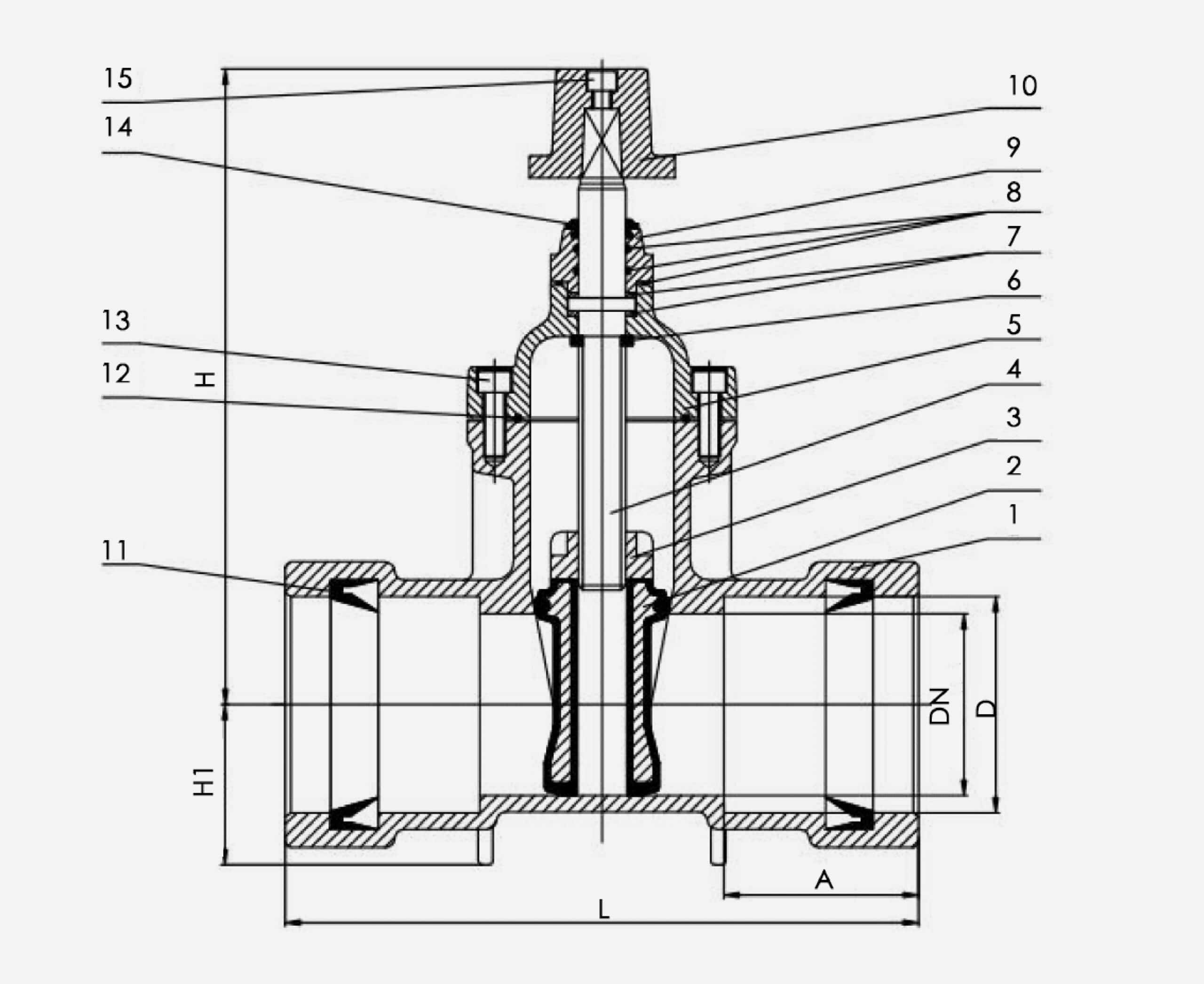
Material specification
| No | Part | Material(ASTM) |
|---|---|---|
| 1 | Body | Ductile Iron ASTM A536 |
| 2 | Wedge | Ductile Iron EPDM/NBR Encapsulated |
| 3 | Wedge Nut | Brass ASTM B124 C37700 |
| 4 | Stem | Stainless Steel AISI 420 |
| 5 | Bonnet | Ductile Iron ASTM A536 |
| 6 | Wedge Nut Gasket | Rubber NBR |
| 7 | Washers | Nylon/Brass ASTM B124 C37700 |
| 8 | O-ring | Rubber NBR |
| 9 | Gland | Ductile Iron ASTM A536 |
| 10 | Operating Nut | Ductile Iron ASTM A536 |
| 11 | Rubber Ring | EPDM/NBR |
| 12 | Bonnet Gasket | Rubber NBR |
| 13 | Bonnet/Gland Bolt | Grand 8 Steel With ZINC Plated |
| 14 | Dust Cap | Rubber NBR |
| 15 | Top Bolts | Stainless Steel AISI304 |
DIMENSIONS (mm)
| inch | L | H | H1 | D | A | |||||
|---|---|---|---|---|---|---|---|---|---|---|
| mm | inch | mm | inch | mm | inch | mm | inch | mm | inch | |
| 2" | 260 | 10.24 | 305 | 12 | 55 | 2.16 | 62.5 | 2.46 | 88.5 | 3.48 |
| 2.5" | 273 | 10.75 | 315 | 12.4 | 68 | 2.67 | 75.7 | 2.97 | 90 | 3.54 |
| 3" | 305 | 12 | 346 | 13.62 | 72 | 2.83 | 92 | 3.62 | 102 | 4.01 |
| 4" | 348 | 13.7 | 395 | 15.55 | 88 | 3.46 | 118.5 | 4.67 | 107 | 4.21 |
| 6" | 428 | 16.85 | 520 | 20.47 | 123 | 4.84 | 173 | 6.81 | 140 | 5.51 |
| 8" | 470 | 18.5 | 595 | 23.43 | 150 | 5.90 | 223 | 8.78 | 155 | 6.10 |
| 10" | 540 | 21.26 | 720 | 28.35 | 185 | 7.28 | 277 | 10.90 | 170 | 6.69 |
| 12" | 672 | 26.46 | 797 | 31.38 | 210 | 8.27 | 328 | 12.91 | 230 | 9.06 |
Feature
Push-Fit Connection
_
● Simple Installation:
The push-fit mechanism allows the valve to be easily connected to pipes by simply pushing the pipe into the valve fitting. This creates a secure and watertight connection.
● No Tools Required:
Typically, no special tools, glue, or soldering are required for installation, making the process faster and easier.
Gate Valve Design
_
● Gate or Wedge:
Similar to other gate valves, it uses a gate or wedge that moves up and down to control the flow of fluid. When the gate is lifted, the flow path is open; when it is lowered, the path is blocked.
● Body:
The body of the valve is usually made from materials such as brass, stainless steel, or plastic, depending on the application.
Operation
_
● Manual or Automated:
Operated manually with a handwheel or lever, or it can be equipped with actuators for automated control.
● Linear Motion:
The gate moves in a linear fashion to block or allow fluid flow, providing a reliable method for isolation.
Application
Residential Plumbing
● Reason:
Push-fit gate valves are commonly used in residential plumbing systems for quick and reliable connections in water supply lines and shut-off valves. Their ease of installation makes them ideal for DIY projects and quick repairs.
Commercial Plumbing
● Reason:
In commercial buildings, these valves are used for water supply, heating, and cooling systems where quick and efficient installation is important.
Heating and Cooling Systems
● Reason:
Suitable for use in HVAC systems for controlling water flow in heating and cooling applications. The push-fit design allows for easy integration and maintenance in complex systems.
Emergency Repairs
● Reason:
Push-fit gate valves are ideal for emergency repairs due to their quick installation and reliable sealing, allowing for fast restoration of water services.
Temporary Installations
● Reason:
Often used in temporary setups where pipes may need to be frequently connected and disconnected, such as in construction sites or event setups.
Installation Steps
Preparation
_
Ensure that the pipe ends are clean and free from any debris or burrs. Cut the pipes to the required length using a pipe cutter.
Mark the Insertion Depth
_
Mark the insertion depth on the pipe to ensure that it is pushed in fully for a secure connection.
Insert the Pipe
_
Push the pipe into the valve fitting until it reaches the marked depth. You should feel some resistance as the pipe passes through the internal O-rings, which create the seal.
Check the Connection
_
Once the pipe is fully inserted, check the connection by pulling slightly on the pipe to ensure it is secure.
Test for Leaks
_
Turn on the water supply and check for any leaks around the connection. If leaks are detected, reinsert the pipe or check the pipe ends for any damage.

