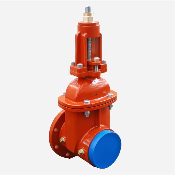
Gate valve is a widely used type of valve designed to control the flow of liquids by lifting a gate (a flat or wedge-shaped disk) out of the path of the fluid.
Gate valve isthe most commonly used valve in the field of water shut off, bi -directional, does not reduce water pressure, can be used above or under ground, simple to operate and easy to maintain.
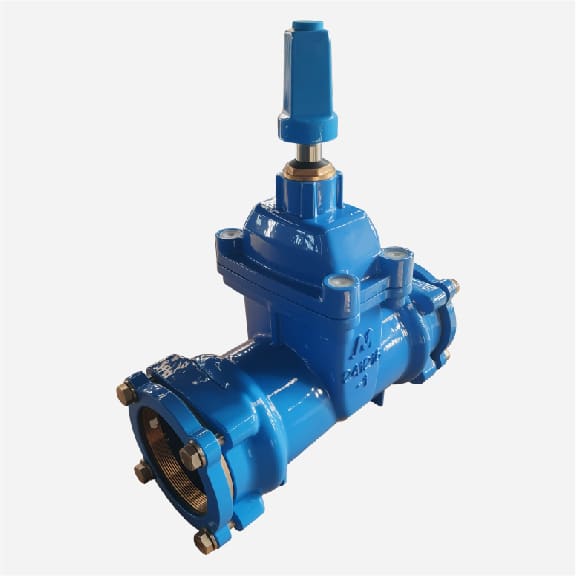
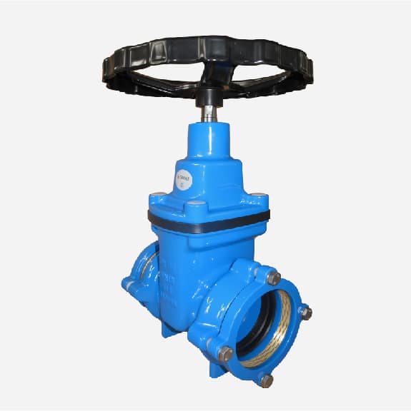
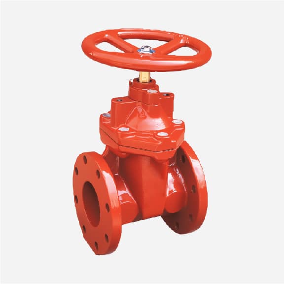
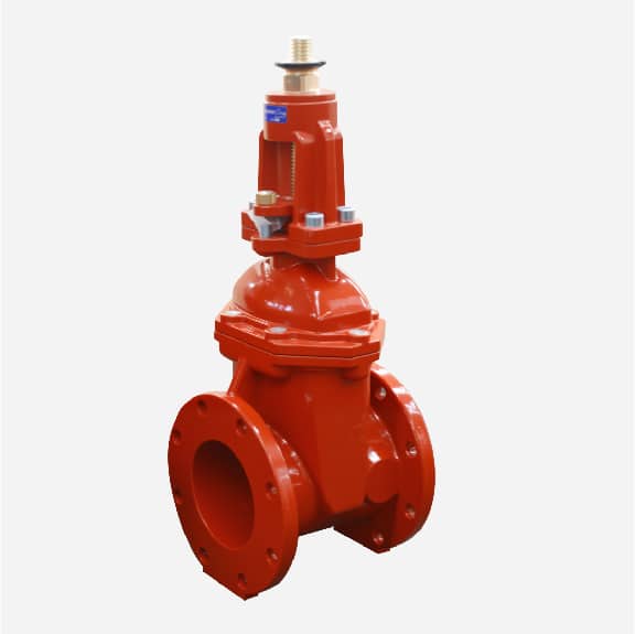
Judberd is china gate valve manufacturer ,we have below types gate valves
1, For Gate Valves, we have CE,UL/FM,WRAS,ACS,DVGW,NSF etc certificate.
2, Our gate valves have the certificate of compliance with EN1074-2, and we have conducted a series of experiments on the valve such as opening and closing times, bending test, etc. in accordance with the requirements of EN1074-2.
3, All production processes of our gate valves are done in-house, so we are able to control all the details of our production, thus ensuring high quality gate valves.
4, Our valve stems are made from a rolling process, which ensures the longevity of the valve and reduces the torque.
5, Our valve wedge are covered with rubber which is very elastic, thus ensuring the longevity of the valve wedge.
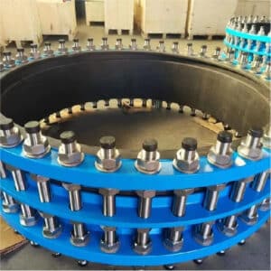
Our casting workshop
Our machining workshop
Our coating workshop
Wedge covering workshop
Our assembling workshop
Our testing workshop
100% quantity pressure test for gate valve according to EN12266-1
FBE coating thickness inspection according to EN14901
Dimension inspection according to EN12266-1
Bend test according to EN1074-2 for gate valve
Number of on-ff tests according to EN1074-2 for gate valve
Torque test according to AWWA C515 for gate valve
GATE VALVE TYPES
Gate valves come in various types, each designed to suit specific applications and operational requirements. Here are the main types of gate valves:
RISING STEM GATE VALVE _
● DESCRIPTION The stem rises as the gate is lifted. The threaded part of the stem is exposed when the valve is open.
● APPLICATIONS Used where space is not constrained and visual indication of valve position is desired.
● ADVANTAGES Easy to determine the valve’s position by the stem’s height.
NON-RISING STEM GATE VALVE _
● DESCRIPTION The stem does not rise. Instead, the gate moves up and down the stem.
● APPLICATIONS Ideal for installations where space is limited, such as underground or in tight spaces.
● ADVANTAGES Requires less vertical space compared to rising stem types.
SOLID WEDGE GATE VALVE _
● DESCRIPTION Features a solid, one-piece wedge as the gate.
● APPLICATIONS Suitable for a wide range of applications, including high-pressure and high-temperature services.
● ADVANTAGES Simple and robust design, providing reliable sealing.
FLEXIBLE WEDGE GATE VALVE _
● DESCRIPTION The wedge is flexible, allowing it to adjust slightly to thermal expansion or contraction.
● APPLICATIONS Used in services where thermal binding might occur, such as steam lines.services where thermal binding might occur, such as
● ADVANTAGES Helps prevent thermal binding and ensures a better seal.
SPLIT WEDGE GATE VALVE _
● DESCRIPTION The gate consists of two pieces that can adjust independently.
● APPLICATIONS Suitable for non-condensing gases and liquids, particularly where the flow is bi-directional.
● ADVANTAGES Provides a tight seal even if the valve body or seat is distorted.
PARALLEL SLIDE GATE VALVE _
● DESCRIPTION The gate slides parallel to the flow direction, with a flat seating surface.
● APPLICATIONS Often used in low-pressure applications.
● ADVANTAGES Reduced risk of sticking and provides a reliable seal without excessive force.
KNIFE GATE VALVE _
● DESCRIPTION Designed with a sharp-edged gate to cut through thick fluids or slurry.
● APPLICATIONS Ideal for handling viscous fluids, slurries, and pulp in industries like paper manufacturing and wastewater treatment.
● ADVANTAGES Effective in cutting through heavy, fibrous material and prevents clogging.
PRESSURE SEAL GATE VALVE _
● DESCRIPTION Designed for high-pressure applications with a pressure seal bonnet that uses system pressure to enhance the seal.
● APPLICATIONS Used in high-pressure steam and hydrocarbon processing applications.
● ADVANTAGES Provides a tighter seal as system pressure increases.
GATE VALVE FUNCTION
Gate valve functions as a control mechanism for regulating the flow of liquid through a pipeline. It operates by raising or lowering a gate (a flat or wedge-shaped disk) to either allow or prevent the flow of fluid. Here are the key functions and operational aspects of a gate valve:
KEY FUNCTIONS _
● On/Off Control Gate valves are primarily used for fully opening or fully closing the flow of liquid. When the valve is fully open, the gate is completely lifted out of the flow path, resulting in minimal resistance and a very low-pressure drop. When the valve is fully closed, the gate blocks the flow, providing an effective seal.
● Isolation Gate valves are often used to isolate sections of a pipeline for maintenance, repair, or inspection. By fully closing the valve, a section of the pipeline can be shut off from the rest of the system.
● Flow Regulation (Limited Use) While gate valves are not typically used for throttling or flow regulation due to the risk of gate and seat damage, they can be partially opened to control flow. However, this is not their primary function, and other types of valves (such as globe valves) are better suited for this purpose.
OPERATIONAL ASPECTS _
● Minimal Flow Resistance When fully open, gate valves provide an unobstructed path for the fluid, resulting in minimal flow resistance and pressure drop. This makes them efficient for applications where maintaining high flow rates is important.
● Bidirectional Flow Gate valves are generally designed to allow flow in both directions, making them versatile for various piping system configurations.
● Leak Tightness When fully closed, gate valves offer a tight seal, effectively preventing any fluid leakage. This makes them suitable for applications requiring a reliable shutoff.
● Manual or Automated Operation Gate valves can be operated manually using a handwheel or automatically with an actuator. Manual operation is straightforward, while actuators can be used for remote or automated control.
APPLICATIONS _
● Water Supply Systems Used to control the flow of water in municipal and residential water supply networks.
● Sewage and Wastewater Systems Employed in sewage systems to control the flow of wastewater.
● Oil and Gas Industry Utilized in pipelines and processing facilities to control the flow of crude oil, natural gas, and other hydrocarbons.
● Industrial Processes Used in various industrial applications where reliable isolation and flow control of liquids are required, such as chemical processing and power plants.
ADVANTAGES _
● Low Pressure Drop Gate valves cause minimal pressure drop when fully open, making them efficient for high flow applications.
● Reliable Sealing Provides a tight seal when fully closed, preventing leaks and ensuring system integrity.
● Versatility Suitable for a wide range of fluids, including water, oil, gas, and slurry.
Disadvantages _
● Slow Operation Gate valves can be slow to open and close, which may not be ideal for applications requiring quick operation.
● Not Ideal for Throttling Partial opening can cause damage to the gate and seat due to high-velocity flow and vibration, making them less suitable for flow regulation.
In summary, gate valves are essential components in many fluid handling systems, providing efficient on/off control, reliable isolation, and minimal flow resistance when fully open.
GATE VALVE WORKING PRINCIPLE
A gate valve works by moving a gate (a flat or wedge-shaped disk) up and down to control the flow of fluid through a pipeline. Here’s a step-by-step explanation of how a gate valve operates:
COMPONENTS OF A GATE VALVE
① HANDWHEEL OR ACTUATOR _
Used to turn the stem, raising or lowering the gate.
② STEM _
The rod that connects the gate to the actuator or handwheel.
③ BONNET _
The part that covers the valve’s opening and holds the stem.
④ BODY _
The main part of the valve that houses the internal components and connects to the pipeline.
⑤ GATE _
The movable disk that blocks or allows flow.
⑥ SEAT _
The sealing surface against which the gate closes to block flow.
OPERATION
OPENING THE VALVE _
● Manual Operation The handwheel is turned counterclockwise, which rotates the stem.
● Automated Operation An actuator (electric, pneumatic, or hydraulic) moves the stem.
As the stem rotates, it lifts the gate out of the flow path. In a rising stem gate valve, the stem moves upward, giving a visual indication of the valve position. In a non-rising stem gate valve, the stem remains in place while the gate moves.
The gate moves away from the seat, creating an unobstructed passage for the fluid to flow through the valve body.
● Fully Open Position When the gate is fully lifted, it is entirely out of the fluid path, resulting in minimal flow resistance and pressure drop.
The valve is now fully open, allowing fluid to pass freely.
CLOSING THE VALVE _
● Manual Operation The handwheel is turned clockwise.
● Automated Operation The actuator moves the stem downward.
As the stem rotates, it lowers the gate back into the flow path.
The gate moves toward the seat, gradually restricting the flow of fluid.
● Fully Closed Position When the gate is fully lowered, it presses tightly against the seat, effectively blocking the flow of fluid.
The valve is now fully closed, providing a leak-tight seal.
KEY POINTS
MINIMAL FLOW RESISTANCE
When fully open, gate valves provide minimal resistance to fluid flow due to the unobstructed path, resulting in a very low-pressure drop.
LEAK-TIGHT SEAL
When fully closed, gate valves offer a reliable seal, preventing any fluid leakage.
NOT FOR THROTTLING
Gate valves are generally not suitable for throttling or regulating flow because partial opening can cause gate and seat damage due to high-velocity flow and vibration.
BIDIRECTIONAL
Gate valves typically allow fluid flow in both directions, making them versatile for various pipeline configurations.
GATE VALVE OPERATION AND MAINTENANCE
How to operate and maintain gate valves correctly, including daily checks, cleaning and troubleshooting, can ensure the long-term reliable operation of the gate valve. Here are detailed steps and suggestions:
OPERATION STEPS
VALVE OPENING AND CLOSING OPERATION
● OPEN THE VALVE
Slowly turn the handwheel or actuator to prevent water hammer caused by too fast opening of the valve.
● CLOSE THE VALVE
Slowly turn the handwheel as well to ensure the valve is fully closed to prevent leakage.
● PRESSURE AND FLOW CONTROL
Ensure that the gate valve operates within its rated pressure and temperature range to avoid overpressure or overheating.
● OPERATION PRECAUTIONS
Avoid exerting excessive force on the valve to prevent damage to the valve stem and seat. Do not use the valve for a long time with the valve partially open, as this will damage the seat and gate.
DAILY CHECKS
● APPEARANCE CHECK
① Check if there is leakage, corrosion or other obvious damage on the outside of the valve.
② Confirm that the valve nameplate and operation label are clearly visible.
● FLEXIBILITY CHECK IN OPERATION
① Turn the handwheel or actuator to ensure smooth operation without jamming.
② Check if the stem is bent, cracked or otherwise damaged.
● SEALING PERFORMANCE CHECK
Check for leakage on the valve sealing surface, especially under high pressure.
CLEANING
● EXTERNAL CLEANING
Wipe the outside of the valve with a soft cloth and appropriate cleaner to remove dust and dirt.
● INTERNAL CLEANING
① Regularly disassemble the valve (according to the manufacturer’s recommendations) to remove deposits and dirt from the seat and gate.
② Ensure that all internal components are clean and dry before reassembly.
TROUBLESHOOTING
● LEAKAGE
① If the valve leaks, first check if the valve is completely closed.
② Check for damage to the sealing surface or foreign objects, and replace the seal if necessary.
● OPERATION NOT SMOOTH
① If the handwheel or actuator is difficult to rotate, check for foreign objects blocking or stem bending.
② Lubricate the stem and actuator to ensure smooth operation.
● UNABLE TO FULLY OPEN OR CLOSE
① Check if there are deposits inside the valve obstructing the gate movement.
② Confirm that the stem thread is intact and replace if damaged.
REGULAR MAINTENANCE
● LUBRICATION
Regularly add lubricant to the stem and other moving parts to ensure smooth operation.
● REPLACE CONSUMABLES
Regularly replace consumables such as seals and gaskets according to the use of the valve and manufacturer’s recommendations.
● PROFESSIONAL INSPECTION
Regularly have professional technicians perform a comprehensive inspection and maintenance to ensure the valve is in optimal condition.
Gate valves can operate stably for a long time in various applications, reducing failures and downtime through correct operation, regular checks and maintenance.
PRESSURE RATING _
● NOMINAL PRESSURE (PN) Usually expressed in MPa or bar, such as PN10, PN16, PN25, etc., applicable to International Standards (ISO), European Standards (EN), and German Standards (DIN)
● AMERICAN STANDARD PRESSURE RATING (CLASS) Such as Class 150, Class 300, Class 600, etc., commonly used in ASME standards.
NOMINAL DIAMETER (DN) _
● INTERNATIONAL STANDARD Such as DN50, DN100, DN150, etc., representing the nominal diameter of the valve, applicable to ISO standards, European Standards (EN), and German Standards (DIN)
● AMERICAN STANDARD SIZE (NPS) Such as NPS 2, NPS 4, representing the pipe size, applicable to ASME standards.
TEMPERATURE RANGE _
● LOW TEMPERATURE Such as -40°C to -196°C, used for low-temperature applications, such as liquefied natural gas.
● ROOM TEMPERATURE Such as -29°C to 150°C, suitable for common industrial applications.
● HIGH TEMPERATURE Such as 150°C to 600°C or higher, used for high-temperature conditions, such as steam systems.
MATERIAL
VALVE BODY MATERIAL _
● CARBON STEEL (WCB) Suitable for water, oil, gas, and other common media.
● STAINLESS STEEL (304, 316) Corrosion-resistant, suitable for chemical, food, pharmaceutical, and other industries.
● CHROME-MOLYBDENUM STEEL (A217 WC9) High-temperature and high-pressure resistant, suitable for steam systems.
● DUCTILE IRON (A395) Suitable for medium and low-pressure water systems.
SEALING MATERIAL _
● POLYTETRAFLUOROETHYLENE (PTFE) Corrosion-resistant, suitable for chemicals.
● RUBBER (NBR, EPDM) Suitable for water, air, etc.
● METAL SEAL (HARD ALLOY) High-temperature and high-pressure resistant, suitable for steam and hot oil.
STRUCTURE TYPE
WEDGE GATE VALVE _
Single wedge, double wedge, and flexible wedge, suitable for most working conditions.
PARALLEL GATE VALVE _
Double gate plates, suitable for conditions requiring bidirectional sealing.
KNIFE GATE VALVE _
Suitable for media such as slurry, sewage, etc., with a cutting function.
OTHER CONSIDERATIONS
DRIVE MODE
● MANUAL Suitable for occasions where operation is not frequent.
● ELECTRIC Suitable for occasions that require automation control.
● PNEUMATIC Suitable for occasions that require quick opening and closing.
INSTALLATION METHOD
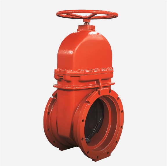
● FLANGE CONNECTION Suitable for most industrial applications, easy to install.
● BUTT-WELD CONNECTION Suitable for high-pressure and high-temperature conditions, firm connection.
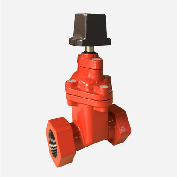
● THREADED CONNECTION Suitable for small-diameter low-pressure systems, easy to install.
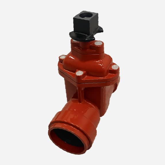
● SOCKET CONNECTION The valve socket and pipe spigot are connected, sealed by a gasket, simple and quick connection.
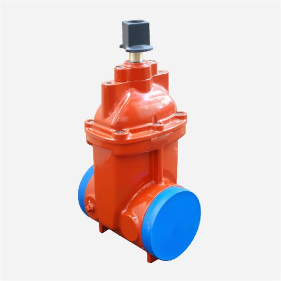
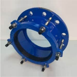
● MECHANICAL INTERFACE CONNECTION Connected by compression nut, bolts, and gaskets. Firm installation.
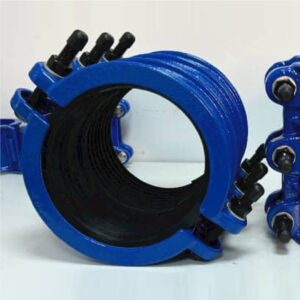
● RESTRAINED CONNECTION The valve interface has a locking device, which can be a locking ring or a locking block to prevent the pipe from coming out, suitable for HDPE pipes that are easy to deform and the ground that is easy to settle.
FLOW COEFFICIENT (CV VALUE)
● CV VALUE Represents the flow through the valve at a certain pressure drop, considering the flow requirements of the system.
By understanding these technical parameters and related standards, you can better select the appropriate gate valve to meet different working conditions and application requirements.
HOW TO CHOOSE THE RIGHT GATE VALVE?
DETERMINE THE APPLICATION SCENARIO
● Fluid type Water: Common in water supply systems, sewage treatment, etc. Requires materials that are corrosion-resistant and wear-resistant.
Oil: Used in petroleum, lubricants, etc., the viscosity and chemical properties of the oil need to be considered.
Gas: Such as natural gas, compressed air, requires good sealing to prevent leakage.
Chemicals: Choose materials that are resistant to chemical corrosion, such as stainless steel or special alloys.
● System Requirements Working environment: Know whether it is installed indoors or outdoors, whether there are extreme temperatures, humidity, or corrosive environments.
Operation conditions: Whether the valve is operated frequently, whether remote control is required, etc.
PRESSURE RATING
● Operating pressure Conventional pressure: Water supply systems generally use PN10, PN16; petrochemicals may require PN25, PN40, or higher.
High-pressure systems: Such as steam systems, industrial gas transportation, may require Class 150, Class 300, Class 600, etc.
● Safety factor Design margin: When choosing a valve, consider a safety factor of 1.5 to 2 times to cope with pressure fluctuations and accidents.
MATERIAL SELECTION
● Common materials Carbon steel: Economical, suitable for non-corrosive media.
Stainless steel: Models such as 304, 316, corrosion-resistant, suitable for chemical, food, and other industries.
Cast iron: Low cost, suitable for low-pressure non-corrosive fluids.
● Special materials Chrome-molybdenum steel: Suitable for high-temperature and high-pressure environments.
Nickel-based alloys: Suitable for strong corrosive media, such as acids, alkalis, etc.
SIZE SELECTION
● Pipeline matching Nominal diameter (DN): Common sizes include DN50, DN100, DN150, etc. When selecting, ensure compatibility with the pipeline system.
Nominal pipe size (NPS): Such as NPS 2, NPS 4, mainly used in American standard systems.
● Flow rate requirements Calculate the flow rate: According to fluid mechanics calculations, select a valve that can meet the maximum flow rate requirements.
Valve diameter: Select a diameter that matches the inner diameter of the pipe to avoid being too large or too small.
TEMPERATURE RANGE
● Low-temperature environment Material selection: In a low-temperature environment, choose materials with good toughness to avoid brittleness.
Sealing material: Choose sealing materials suitable for low temperatures, such as PTFE.
● High-temperature environment High-temperature materials: Such as chrome-molybdenum steel, stainless steel, etc., can maintain strength and corrosion resistance.
Temperature fluctuation: Consider the temperature fluctuation range to ensure that the valve material can perform stably over the entire temperature range.
SPECIAL REQUIREMENTS
● Fire safety Fire valve: Choose valves that meet fire standards such as API 607 or BS 6755 for use in flammable and explosive environments.
Fire-resistant materials: Choose heat-resistant sealing materials and valve body materials.
● Hygienic grade Food-grade stainless steel: Choose stainless steel materials that meet FDA or 3A standards for use in food, pharmaceuticals, and other industries.
Easy-to-clean design: Ensure there are no dead angles inside the valve, making it easy to clean and disinfect.
OTHER CONSIDERATIONS
● Operation method Manual: Suitable for systems that are not operated frequently.
Pneumatic: Suitable for systems that need to open and close quickly, such as emergency shut-off.
Electric: Suitable for systems with high automation, making it convenient for remote control.
● Special materials Chrome-molybdenum steel: Suitable for high-temperature and high-pressure environments.
Nickel-based alloys: Suitable for strong corrosive media, such as acids, alkalis, etc.
SUMMARY
Choosing the right gate valve is a process of comprehensive consideration of system requirements, working conditions, and economy.
By carefully evaluating the following factors: application scenarios, pressure ratings, materials, sizes, temperature ranges, special requirements, and other considerations, you can ensure that the selected valve operates reliably under expected conditions, improving system safety and efficiency.
GATE VALVE INSTALLATION
The correct installation method and precautions for gate valves vary depending on the type of connection. Here are installation guides for gate valves for various connection types:
FLANGE CONNECTION
INSTALLATION METHOD
● Preparation
Check if the flange surface is clean and flat, free of impurities and damage.
Use appropriate gaskets, such as rubber gaskets, metal gaskets, etc.
● Installation steps
Align the flange valve with the pipe flange and insert the appropriate gasket.
Secure with bolts and nuts, tighten the bolts evenly on both sides alternately to ensure a uniform seal.
● Precautions
Ensure the flange surface is clean and undamaged.
Use the appropriate bolt torque to avoid overtightening or loosening the bolts.
Regularly check the sealing at the flange connection.
BUTT-WELD CONNECTION
INSTALLATION METHOD
● Preparation
Clean the welding end of the valve and pipe, free of oil and rust.
Check if the butt size of the welding end matches.
● Installation steps
Align the valve welding end with the pipe and tack weld it in place.
After tack welding, complete the full weld according to the specified welding process to ensure a flat and even weld.
● Precautions
Ensure the welding quality to avoid weld defects.
The valve is in the half-open position during welding to prevent valve deformation during welding.
After welding, perform a pressure test to ensure no leaks.
THREADED CONNECTION
INSTALLATION METHOD
● Preparation
Inspect the threaded section to ensure no damage and impurities.
Use an appropriate amount of sealant or sealing tape.
● Installation steps
Align the valve with the pipe threaded end, manually rotate to connect, and ensure alignment.
Use a wrench to tighten appropriately, but avoid overtightening to prevent thread damage.
● Precautions
Ensure the threaded section is clean and undamaged.
Avoid overtightening to prevent thread damage.
Regularly check the sealing at the threaded connection.
SOCKET CONNECTION
INSTALLATION METHOD
● Preparation
Clean the valve socket and pipe spigot, free of impurities.
Apply an appropriate amount of lubricant to the gasket for easy installation.
● Installation steps
Place the gasket in the socket’s sealing groove.
Insert the pipe spigot into the valve socket, use the appropriate tool to push it in place.
● Precautions
Ensure the gasket is intact and lubricated.
Apply even force when inserting the socket to avoid excessive force.
Regularly check the gasket’s sealing performance to prevent leaks due to aging.
MECHANICAL INTERFACE CONNECTION
INSTALLATION METHOD
● Preparation
Clean the connection ends of the valve and pipe, free of impurities.
Prepare gland, bolts, and gaskets.
● Installation steps
Place the gasket on the pipe connection end, insert it into the valve connection, and push it in place.
Fix with the gland and bolts, tighten the bolts evenly on both sides alternately to ensure a uniform seal.
● Precautions
Ensure the gasket and gland are intact and undamaged.
Use the appropriate bolt torque to avoid overtightening or loosening the bolts.
Regularly check the sealing and fastening of the mechanical interface.
RESTRAINED CONNECTION
INSTALLATION METHOD
● Preparation
Clean the connection ends of the valve and pipe, free of impurities.
Prepare the locking device, such as a locking ring or locking block.
● Installation steps
Insert the pipe into the valve interface, install the locking device to ensure the pipe does not come out.
Tighten the locking device evenly according to the manufacturer’s requirements to ensure a secure fit.
● Precautions
Ensure the locking device is installed correctly to prevent the pipe from coming out.
Use the appropriate tools and methods to avoid damaging the locking device.
Regularly check the fastening of the locking device to ensure safety and reliability.
GENERAL PRECAUTIONS
● Installation direction
Ensure the installation direction of the valve is consistent with the flow direction of the medium.
● Environmental conditions
Avoid installation in extreme temperature and humidity environments to prevent damage to the valve and connections.
● Sealing check
After installation, perform a pressure test and check the sealing at all connections.
● Maintenance
Regularly check the condition of the valve and its connecting parts, and perform maintenance and replacement in a timely manner.
By correctly installing the gate valve according to the above guidelines and paying attention to the specific requirements of each connection type, you can ensure the reliable operation of the valve and the safety of the system.
SEWAGE GATE VALVE
Sewage is a general concept, before choosing a valve, we need to know what kind of sewage, whether the sewage is corrosive, what is the temperature? Is there any impurities in the sewage, and if there are impurities, what kind of impurities etc.
in order to know what type valve to choose. If the sewage is corrosive to the rubber of the resilient seated gate valve or the high temperature that the resilient seated gate valve can not withstand, we have to choose the metal seated gate valve.
If there are impurities inside the sewage, impurities are hard, easy to accumulate in the groove where the metal seated gate valve body and valve wedge contact, when closing the wedge, hard impurities are easy to choke the gate valve sealing ring, then we have to choose the resilient seated gate valve that is inclusive of hard impurities.